
Deinking device and method for waste paper magnetic-separation deinking machine

A deinking machine and magnetic separation technology, applied in the processing of waste paper, chemical instruments and methods, papermaking, etc., can solve the problems of difficult washing or flotation, poor deinking effect, difficult treatment, etc. The effect of increasing the deinking concentration and improving the recovery rate

Inactive Publication Date: 2012-09-19
有研资源环境技术研究院(北京)有限公司
View PDF5 Cites 3 Cited by
  • Summary
  • Abstract
  • Description
  • Claims
  • Application Information

AI Technical Summary

Problems solved by technology

Another example is that some inks have irregular shapes after pulping, such as laser printing and copying waste paper of office waste paper, which are non-contact printing inks containing thermoplastic resins. The deinking method is difficult to handle, neither easy to wash or float (large or irregular particle size), and not easy to handle with deslagging or screening equipment (too small particle size)
When such inks are processed by conventional deinking methods such as flotation and washing, the following disadvantages exist: high fiber loss (20-25%); large amount of solid waste; high cost; low deinking efficiency
However, the magnetic separators with several structures are used for magnetic separation deinking, and are not easy to be absorbed by the drum of the magnetic separator, causing the magnetic material (ink) to flow out of the good pulp (deinked pulp), so that the deinking effect is poor.

Method used

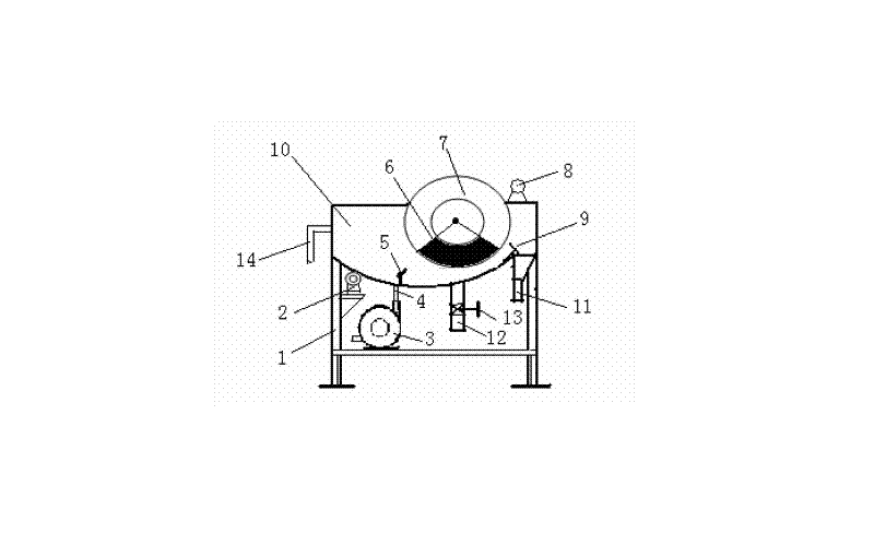
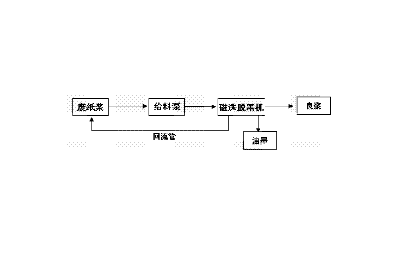
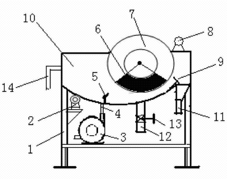

Image

  • Deinking device and method for waste paper magnetic-separation deinking machine
  • Deinking device and method for waste paper magnetic-separation deinking machine
  • Deinking device and method for waste paper magnetic-separation deinking machine

Examples


Embodiment 1

[0036] Example 1: Office waste paper with a whiteness of 89% ISO is prepared into a slurry with a concentration of 3-4w%. After being treated by this device, high-grade cultural paper with a whiteness of 95% can be obtained with a fiber loss of 5%.

Embodiment 2

[0037] Example 2: Waste magazine paper with a brightness of 73% ISO is prepared into a slurry with a concentration of 3-4w%. After being treated by this device, cultural paper with a brightness of 89% can be obtained, and the fiber loss is 7%.

[0038] The waste paper magnetic separation deinking device and deinking method of the present invention, the pulp is fed into the pulp from the bottom pressure, the dispersion degree of the pulp is improved, the entrainment of the magnetic substance to the paper fiber is reduced, and the magnetic substance (ink) is easily adsorbed on the magnetic drum , thus improving the deinking rate and fiber yield. It can be magnetically separated with a higher pulp concentration, which improves the processing capacity.


PUM

PropertyMeasurementUnit
Angleaaaaaaaaaa

Abstract

The invention relates to a deinking device and a method for a waste paper magnetic-selected deinking machine, and relates to the field of waste paper deinking reuse. The deinking device comprises a frame, a transmission system, a feeding pump, a feeding pipe, a weir plate, a rotating drum, an unloading water pipe, a separation tank body, a printing ink discharging pipe, an accept discharging pipe, and a return pipe, wherein permanent magnets are arranged in the rotating drum; the separation tank body is disposed in a lower portion of the rotating drum; the printing ink discharging pipe, the accepts discharging pipe, and the return pipe are arranged on the separation tank body; valves for adjusting liquid level is disposed on the accept discharging pipe; and a stability of the liquid level in the separation tank body is maintained by the return pipe. By feeding the paper pulp from the bottom, the device improves the dispersion degree of the paper pulp and reduces the entrainment of the magnetic materials to the paper fibers, and the magnetic materials (printing inks) is easy to adsorb on the magnetic rotating drum, so that the deinking rate and the fiber receiving rate are improved, magnetic separation can be realized in a relatively high concentration of the paper pulp, and the processing capability is improved.

Description

technical field [0001] The invention relates to a deinking device of a waste paper magnetic separation deinking machine and a method thereof, belonging to the field of waste paper deinking and reuse. Background technique [0002] Waste paper has long been used as one of the raw materials for the paper industry. Waste paper contains a variety of impurities, such as ink, pigments and stickies. Flotation and washing are currently the main deinking processes. The former is separated by the preferential adsorption of the ink detached from the paper to the air bubbles, and the latter is separated from the fibers by the relative flow of water and fibers to separate small particles. Both need to add a large amount of chemical agents, such as sodium hydroxide, sodium silicate, chelating agent, hydrogen peroxide, surfactant, collector, coagulant, dispersant, etc. Undoubtedly, adding such a large amount of complex and high-alkaline chemicals will have adverse consequences, cause ser...

Claims


Application Information

Patent Timeline
IPC IPC(8): D21C5/02B03C1/10
CPCY02W30/64
Inventor 郑其车小奎段锦韩利生
Owner 有研资源环境技术研究院(北京)有限公司
Learn More