Thermodynamic system for combined heat recovery of power plant

A technology of thermal system and thermal cycle system, applied in the field of recycling to regenerative system, can solve the problems of heat loss, single function of heat recovery of flue gas, large pressure fluctuation of deaerator, etc., to reduce coal consumption, improve thermal cycle efficiency, The effect of reducing the loss of cold source

Active Publication Date: 2012-09-19
CHINA POWER ENG CONSULTING GRP CORP EAST CHINA ELECTRIC POWER DESIGN INST
View PDF6 Cites 15 Cited by
  • Summary
  • Abstract
  • Description
  • Claims
  • Application Information

AI Technical Summary

Problems solved by technology

[0010] The purpose of the present invention is to solve the above problems. It provides a combined heat recovery thermal system of a power plant. It optimizes and recycles the flue gas heat recovery system and the small machine exhaust system of steam-driven equipment, improves the exhaust system, and solves the problem of Problems such as large pressure fluctuations in the deaerator, difficult exhaust pipe layout, heat loss, complex operation control methods, single flue gas heat recovery function, and high possibility of low-temperature corrosion have been solved.

Method used


Image

  • Thermodynamic system for combined heat recovery of power plant
  • Thermodynamic system for combined heat recovery of power plant
  • Thermodynamic system for combined heat recovery of power plant

Examples


no. 1 example

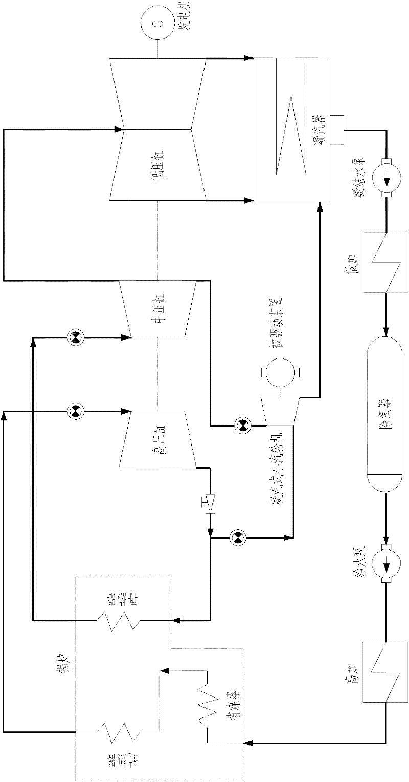
[0033] Figure 4 It shows the structure of the first embodiment of the combined heat recovery thermal system of the power plant of the present invention. See Figure 4 , The system of this embodiment includes a fan exhaust steam waste heat recovery heater 10, a regenerative driving steam turbine 11, a drain pump 12, a flue gas waste heat recovery device 13, and an atmospheric expansion vessel 14 for exhaust steam. The flue gas waste heat recovery device 13 provides a separate external heat source for the thermal cycle system of the power plant, and the fan exhaust waste heat recovery heater on the fan side is connected in series or parallel to the thermal cycle system of the unit.

[0034] The fan exhaust waste heat recovery heater 10 is located at the fan side, that is, a first-stage fan exhaust waste heat recovery heater 10 is added to the original thermal cycle heat recovery system. The steam in the thermal cycle system of the power plant is connected to the regenerative ...

no. 3 example

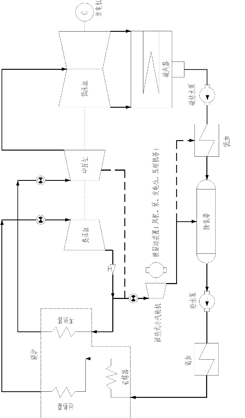
[0055] Figure 6 It shows the structure of the third embodiment of the combined heat recovery thermal system of the power plant of the present invention. See Figure 6 , The system of this embodiment includes a fan exhaust steam waste heat recovery heater 30, a regenerative drive steam turbine 31, a drain pump 32, a flue gas waste heat recovery device 33, and an expansion vessel 34 for exhaust steam. The flue gas waste heat recovery device 33 provides a separate external heat source for the thermal cycle system of the power plant, and the fan exhaust waste heat recovery heater on the fan side is connected in series or parallel to the thermal cycle system of the unit.

[0056] The fan exhaust waste heat recovery heater 30 is located at the fan side, that is, a first-stage fan exhaust waste heat recovery heater 30 is added to the original thermal cycle heat recovery system. The steam in the thermal cycle system of the power plant is connected to the regenerative drive steam tu...


PUM


Abstract

The invention discloses a thermodynamic system for combined heat recovery of a power plant. A smoke heat recovery system and a small exhaust system of turbine driven equipment are optimized for combined recovery. The technical scheme is as follows: the system comprises a fan exhaust afterheat recovery heater located on the fan side, a drainage pump and a smoke afterheat recovery device, wherein steam in a thermodynamic cycle system of the power plant is accessed into a regenerative driving steam turbine on the fan side to act; exhaust steam of the regenerative driving steam turbine enters the fan exhaust afterheat recovery heater, and the exhaust afterheat is utilized by the fan exhaust afterheat recovery heater to heat the water for heating; the drainage pump is connected with a water pipe at the outlet of the fan exhaust afterheat recovery heater or a water pipe at the inlet of the fan exhaust afterheat recovery heater for returning the water to the outlet or inlet of the fan exhaust afterheat recovery heater; and the smoke afterheat recovery device is used for receiving the water for heating at the outlet of the heater in the thermodynamic cycle system of the power plant and exchanging heat with the smoke.

Description

technical field [0001] The invention relates to an energy recovery technology, in particular to a technology for combining waste heat such as flue gas and exhaust steam of a regenerative driving steam turbine in a power plant, and recovering it to a regenerative system. Background technique [0002] Waste heat refers to the sensible heat and latent heat that have not been rationally utilized in the original design in the energy-consuming devices of industrial enterprises that have been put into operation due to the limitations of history, technology, ideas and other factors. It includes waste heat of high-temperature exhaust gas, waste heat of cooling medium, waste heat of waste steam and waste water, waste heat of high-temperature products and slag, waste heat of chemical reaction, waste heat of combustible waste gas and liquid, waste heat, etc. [0003] At present, the waste heat loss of exhaust smoke and exhaust steam of generator sets in my country is relatively large, w...

Claims


Application Information

Patent Timeline
Patent Type & Authority Applications(China)
IPC IPC(8): F01K17/02
CPCY02E20/14
Inventor 陈彦申松林叶勇健林磊董伦雄施刚夜
Owner CHINA POWER ENG CONSULTING GRP CORP EAST CHINA ELECTRIC POWER DESIGN INST
Why Eureka
Try Eureka