Static balance test method applied to gyroscope position marker spindle

A test method and a technology of a position marker, which are applied in the direction of speed measurement by gyro effect, gyroscope/steering sensing equipment, instruments, etc., can solve the problems of high test environment requirements, static unbalance of the position mark, and contamination of the position mark and other problems, to achieve the effect of low test environment requirements, simple test data processing, and high test accuracy indicators

Inactive Publication Date: 2012-09-19
BEIHANG UNIV
View PDF2 Cites 10 Cited by
  • Summary
  • Abstract
  • Description
  • Claims
  • Application Information

AI Technical Summary

Problems solved by technology

Usually due to design errors, material defects, processing and assembly errors, etc., the mass eccentricity of the inner ring axis, middle ring axis and outer ring axis of the gyro marker will be caused, which will cause the static unbalance of the gyro marker. If the unbalance is too large, The additional dynamic pressure will not only accelerate the bearing damage, but also cause the vibration of the entire seeker, accelerate the mechanical wear of the marker, and even cause the seeker system to lose control. Therefore, the static unbalance of the gyro shaft of the marker It is particularly important to study the position characteristics of static unbalance
[0003] Although the traditional rolling method, weighing balance method, and static pressure support method have cleverly solved the problem of the static balance test of the gyro shaft of the position marker, but these methods have a large friction force during the test process, and it is difficult to achieve a high level of stability. High balance accuracy, sensitivity is difficult to guarantee, and when there are scratches, bumps, rust, and dirt on the mating surface, on the one hand, it will cause contamination of the measured position marker, on the other hand, it will be disassembled during the measurement process The work is cumbersome and the counterweight process is complicated; although the optical adjustment method overcomes the shortcomings of the above methods to a large extent, it has high requirements for the test environment, poor adaptability, troublesome operation process, and difficult to improve test efficiency

Method used


Image

  • Static balance test method applied to gyroscope position marker spindle
  • Static balance test method applied to gyroscope position marker spindle
  • Static balance test method applied to gyroscope position marker spindle

Examples


Embodiment Construction

[0025] The present invention will be further described in detail with reference to the accompanying drawings and embodiments.

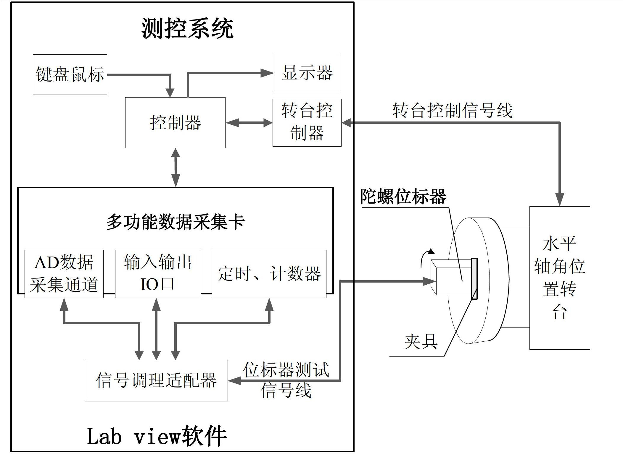
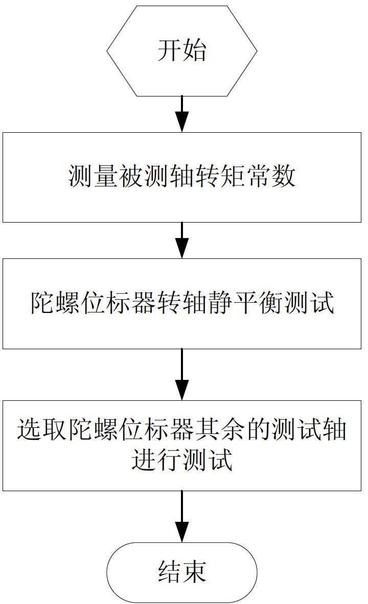
[0026] The present invention relates to a static balance test method for the rotating shaft of a gyro position marker. The structural composition diagram of the system used is as follows figure 1 As shown, the whole system is mainly composed of the tested gyro marker, the horizontal axis angular position turntable, various fixtures and measurement and control systems. The objects of the static balance test are the outer ring, middle ring and inner ring of the gyro marker. When testing the rotating shaft and the system, first use various fixtures to mount the gyro marker on the turntable at the angular position of the horizontal axis, and adjust any one of the three axes of the gyro marker to be measured with the turntable by changing the direction of the installation fixture. The horizontal axis is parallel, and the system monitoring software compiled...


PUM


Abstract

The invention discloses a static balance test method applied to a gyroscope position marker spindle. A horizontal axis angular position rotary table is used for mounting and clamping a gyroscope position marker to be tested, any one axis to be tested of the gyroscope position marker is parallel to the horizontal axis of the rotary table by adjusting direction of a mounting fixture, a measurement and control system drives the tested axis to complete sine small angle vibration at each locking angular position of the rotary table, value of a static unbalance can be solved by virtue of integration on measured quantities in a driving current period of the tested axis, and position of the static unbalance can be obtained by observing the driving current and an angular position signal and combining a corner of the horizontal rotary table. The concrete test process comprises the following steps of: step one, measuring torque constant of the tested axis; step two, carrying out static balance test on the gyroscope position marker spindle; and step three, selecting the rest test axes of the gyroscope position marker and carrying out test, after the tested axis is determined, repeating the step one and the step two, and finally completing test on three tested axes, namely an outer annular axis, a middle annular axis and an inner annular axis, thus the test method disclosed by the invention is finished.

Description

technical field [0001] The invention relates to a static balance test method for a rotating shaft of a gyro marker, belonging to the technical field of automatic detection and calibration of a gyro marker. Background technique [0002] The gyro position marker is the core component to realize the target detection, optical axis stabilization, follow-up and tracking of the missile guidance system. It is generally composed of a mechanical platform, a three-axis frame, a gyro rotor, a servo motor, a torquer and a control circuit. Usually due to design errors, material defects, processing and assembly errors, etc., the mass eccentricity of the inner ring axis, middle ring axis and outer ring axis of the gyro marker will be caused, which will cause the static unbalance of the gyro marker. If the unbalance is too large, The additional dynamic pressure will not only accelerate the bearing damage, but also cause the vibration of the entire seeker, accelerate the mechanical wear of th...

Claims


Application Information

Patent Timeline
Patent Type & Authority Applications(China)
IPC IPC(8): G01C19/5663
Inventor 赵剡杨辉吴发林王志龙野超
Owner BEIHANG UNIV
Why Eureka
Try Eureka