Method for measuring time delay by synchronous signal trigger sweep

A technology of synchronization signal and delay time, which is applied in the field of delay time measurement of synchronization signal-triggered scanning method, can solve problems such as the deviation of the starting point of exposure and absolute graphic position, and achieve the effect of solving absolute positioning accuracy and improving absolute positioning accuracy.

Active Publication Date: 2012-09-19
中夏芯基(上海)科技有限公司
View PDF5 Cites 13 Cited by
  • Summary
  • Abstract
  • Description
  • Claims
  • Application Information

AI Technical Summary

Problems solved by technology

[0003] The purpose of the present invention is to provide a method for measuring the delay time of the scanning mode triggered by a synchronous signal, so as to solve the problem of deviation between the starting point of exposure and the absolute pattern position due to the delay of the trigger signal in the lithography machine system in the prior art

Method used


Image

  • Method for measuring time delay by synchronous signal trigger sweep
  • Method for measuring time delay by synchronous signal trigger sweep
  • Method for measuring time delay by synchronous signal trigger sweep

Examples


Embodiment Construction

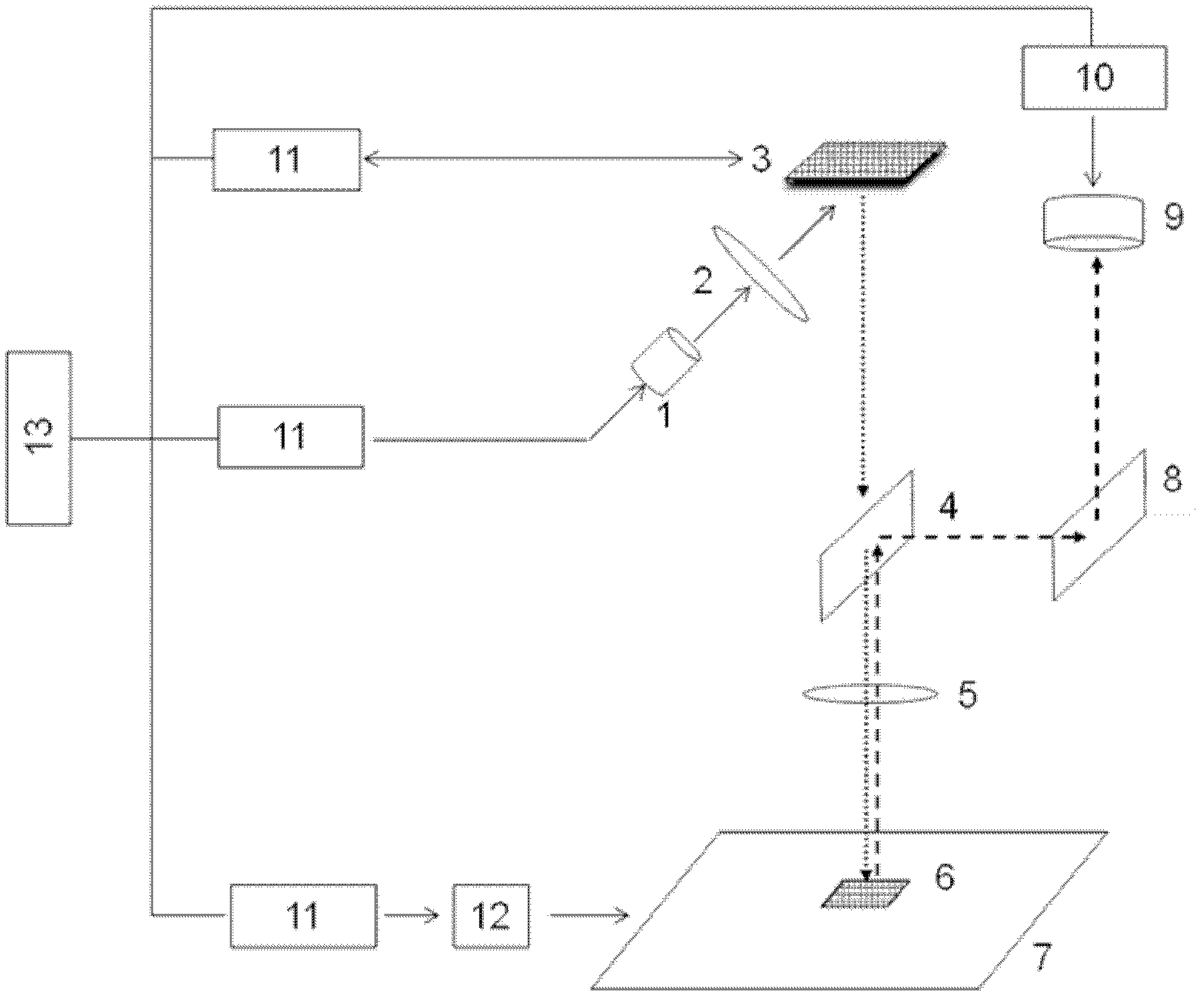
[0023] like Figure 1-4 As shown, the method for measuring the delay time of the scanning mode triggered by a synchronous signal includes a projection exposure module and a main control module. The projection exposure module includes an exposure light source 1 and a spatial light modulator 3. There is an optical light collection system 2, an inclined beam splitter 4 is arranged under the spatial light modulator 3, a base 6 is arranged under the beam splitter 5, and a lens (group) 5 is also arranged between the beam splitter 4 and the base 6, A reflector 8 is provided on the front optical path of the splitting surface of the beam splitter 4, a CCD camera 9 is arranged on the front optical path of the reflected light of the reflector 8, and the substrate 6 is placed on the precision mobile platform 7; the main control module includes a computer system 13. The controller 11 and the computer system 13 are respectively controlled and connected to the spatial light modulator 3, ...


PUM


Abstract

The invention discloses a method for measuring time delay by synchronous signal time sweep. Pulse signals are equidistantly triggered at different speeds along a positive direction of a precise mobile platform to a spatial light modulator which exposes two frames different in sizes at the same center position to imaging on a substrate surface, the time delay from the outputting of synchronous signals to the image displaying of the spatial light modulator is calculated by measuring a positional deviation of the exposed frames, then the exposure can be compensated according to the time delay. The method for measuring time delay by synchronous signal time sweep can accurately expose the image to a designated position, absolute positioning accuracy of the exposed image is improved, and absolute positioning accuracy error of the exposed image caused by different exposure speeds is avoided simultaneously.

Description

technical field [0001] The invention relates to the technical field of lithography in the semiconductor industry, is mainly applied in an optical maskless lithography system, and specifically relates to a method for measuring delay time of a scanning mode triggered by a synchronous signal. Background technique [0002] The lithography machine is one of the main integrated circuit equipment in the semiconductor manufacturing industry. As the core component of the lithography machine, the precision mobile platform is used to realize functions such as fast movement and precise positioning. The rapid exposure of the lithography machine system is realized by using the position synchronization signal to trigger scanning. Its working principle is: define the starting point position of the exposure in advance, the position interval of the trigger pulse, and output the pulse according to the set trigger mode as the platform moves at a constant speed signal to achieve synchron...

Claims


Application Information

Patent Timeline
Patent Type & Authority Applications(China)
IPC IPC(8): G03F7/20
Inventor 毕娟朱亮
Owner 中夏芯基(上海)科技有限公司
Why Eureka
Try Eureka