
Shell-type transformer with improved heat dissipation performance

A technology for shell-type transformers and heat dissipation performance, which is applied in the directions of transformer/inductor cooling, transformer/inductor core, transformer/inductor coil/winding/connection, etc., which can solve the complex process of high-voltage winding layout, increase loss and heat , Insufficient insulation strength and other problems, to achieve the effect of reducing the uneven distribution of temperature, reducing resistance, and low end temperature

Active Publication Date: 2012-09-19
SHANGHAI JIAO TONG UNIV
View PDF7 Cites 6 Cited by
  • Summary
  • Abstract
  • Description
  • Claims
  • Application Information

AI Technical Summary

Problems solved by technology

A search of existing technical documents found that the document "1Megawatt, 20kHz, Isolated, Bidirectional 12kV to 1.2kV DC-DCConverter for Renewable Energy Applications" (The 2010 International Power Electronics Conference) proposed a single-phase core transformer heat dissipation structure, in each A water-cooled heat sink is placed between each iron core column and the low-voltage winding. The disadvantage of this heat dissipation method is that the leakage magnetic field on the heat dissipation structure causes eddy currents, which increases additional loss and heat. In addition, a water deionization device is required.
This document also proposes a similar shell-type transformer, which adopts the heat dissipation method of aluminum plates and heat sinks on the upper and lower yokes respectively; the document also proposes another matrix transformer structure, in which each low-voltage winding is independent, and the high-voltage winding is shared and a layer is established. The two structures are not only bulky, but also the high-voltage winding layout process for establishing the ventilation channel is complicated.
The above three heat dissipation structures are feasible for 12kV dry-type transformers, but the insulation strength of transformers with voltage levels higher than 35kV is insufficient

Method used


Image

  • Shell-type transformer with improved heat dissipation performance
  • Shell-type transformer with improved heat dissipation performance
  • Shell-type transformer with improved heat dissipation performance

Examples


Embodiment Construction

[0023] Embodiments of the present invention are described in detail below, and the present embodiment is implemented on the premise of the technical solution of the present invention, and detailed implementation and specific operation process are provided, but the protection scope of the present invention is not limited to the following embodiments.

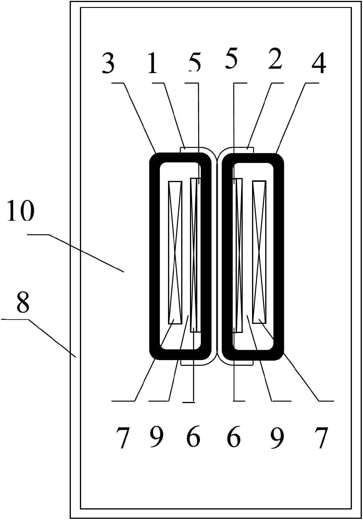
[0024] The problem to be solved in this embodiment is to find a non-forced heat dissipation method with simple structure and process, small size and light weight, which can effectively reduce the maximum temperature of the inner core column and winding of the thin and tall shell type amorphous alloy transformer. Lift.

[0025] In this embodiment, the high-voltage winding of the medium-frequency amorphous alloy transformer is 50 kV, and the modular composite shell structure is adopted, which significantly reduces the height of the iron core and yoke, thereby reducing the unevenness of the magnetic field inside the iron core. Moreo...


PUM

PropertyMeasurementUnit
Thicknessaaaaaaaaaa

Abstract

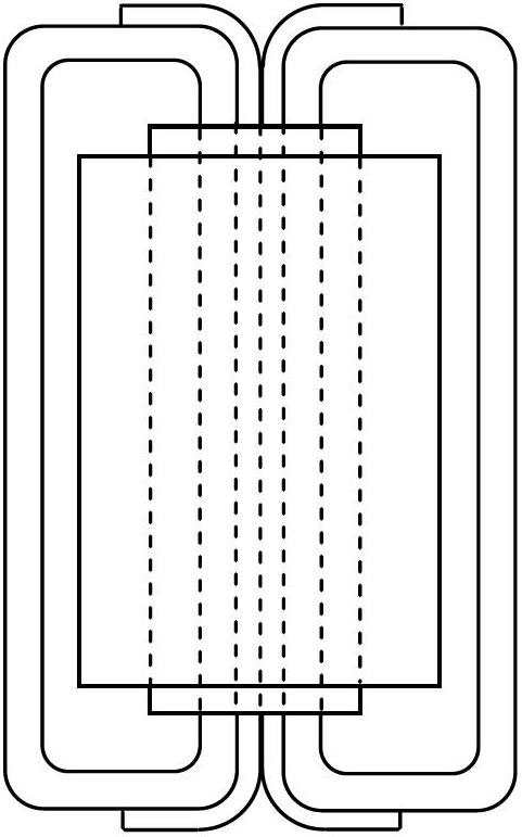
The invention discloses a shell-type transformer with improved heat dissipation performance. The shell-type transformer comprises a left iron core, a right iron core, a low-voltage winding and iron core column insulator, a low-voltage winding, a high-voltage winding, an oil tank, an oil channel and transformer oil, wherein the iron cores are placed in the middle of the oil tank; the oil tank is filled with the transformer oil; a heat conduction sheet clings to the left and right iron cores; a heat dissipation oil channel is arranged between the low-voltage winding and the high-voltage winding; the heat conduction sheet derives the heat of the middle iron core column along the heat conduction sheet toward upper and lower sides; and the heat dissipation oil channel cools the low-voltage winding and the high-voltage winding and performs natural convection cooling through the transformer oil.. Through the invention, the heat dissipation conditions on the middle iron core column and the surrounding windings of the slim and tall intermediate-frequency amorphous alloy shell-type transformer are effectively improved, and thus the maximum temperature rise of the transformer is reduced. According to the invention, the structure process is simple, the heat conduction sheet does not generate heat, the occupied space is small, an external power supply such as a cooling fan is not needed, and thus the shell-type transformer is suitable for an environment of an offshore wind power generation platform and the like with relatively severe working conditions.

Description

technical field [0001] The invention relates to a heat dissipation technology for a transformer, in particular to a shell-type transformer with improved heat dissipation performance. Background technique [0002] The use of renewable wind energy is shifting from land to sea. In offshore wind power generation, the AC transmission of submarine cables has large reactive power fluctuations, and DC transmission can overcome this shortcoming, which will become the development trend of offshore power transmission in the future. In addition, the onshore distributed power generation system is easier to realize multi-terminal connection by using DC grid than AC grid. In order to realize low-voltage DC to high-voltage DC conversion, a kilohertz-level intermediate frequency transformer must be used. Under medium frequency conditions, amorphous alloys are thinner than electrical silicon steel strips, and have the characteristics of less loss than iron cores. Moreover, the power densit...

Claims


Application Information

Patent Timeline
IPC IPC(8): H01F27/08H01F27/12H01F27/28H01F27/24F28F3/00
Inventor 谢宝昌张涵蔡旭
Owner SHANGHAI JIAO TONG UNIV
Learn More