Chip reinforced boiling heat transfer structure of multi-pore microcolumn variable camber molded surfaces

A technology to enhance boiling and heat transfer structure, applied in electrical components, electrical solid devices, circuits, etc., can solve the problems of heat transfer deterioration on the surface of heating components, unfavorable liquid heating surface, increased fluid flow resistance, etc., to achieve the elimination of boiling The effect of increasing the initial temperature rise, improving the liquid transport efficiency, and reducing the fluid flow resistance

Inactive Publication Date: 2012-09-19
XI AN JIAOTONG UNIV
View PDF2 Cites 41 Cited by
  • Summary
  • Abstract
  • Description
  • Claims
  • Application Information

AI Technical Summary

Problems solved by technology

Therefore, many researchers focus on the slotting method of porous surface mainly to open rectangular micro-grooves on the surface of the porous structure, and increase the effective area of ​​capillary action to improve the heat transfer of nucleate boiling. However, for the ultra-high heat flux boiling area, the heat transfer on the surface of the heating element deteriorates, and the heat flux value increases linearly with the superheat degree of the wall surface, and the study found that the critical heat flux has the same relationship wit

Method used


Image

  • Chip reinforced boiling heat transfer structure of multi-pore microcolumn variable camber molded surfaces
  • Chip reinforced boiling heat transfer structure of multi-pore microcolumn variable camber molded surfaces
  • Chip reinforced boiling heat transfer structure of multi-pore microcolumn variable camber molded surfaces

Examples


Embodiment Construction

[0024] The present invention will be described in further detail below in conjunction with the accompanying drawings.

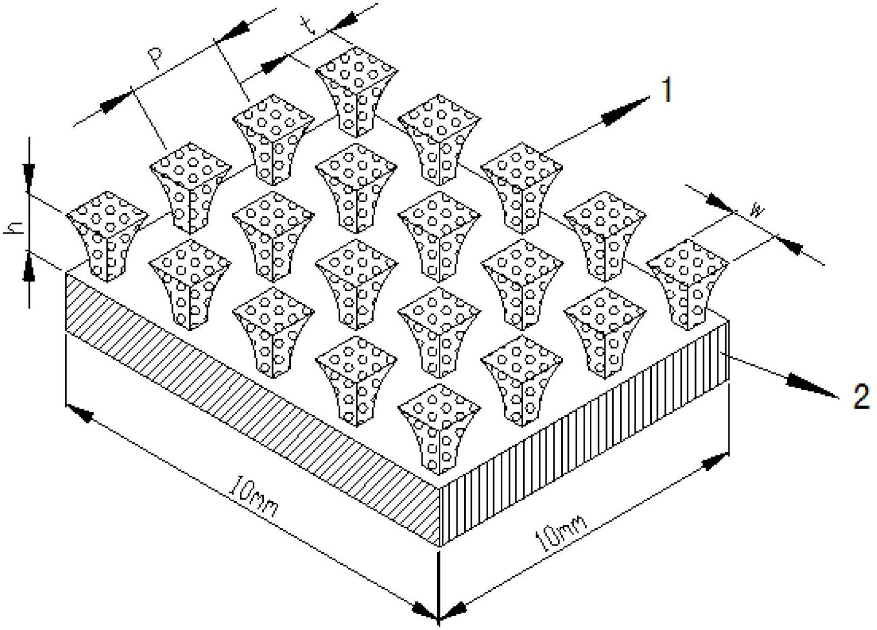
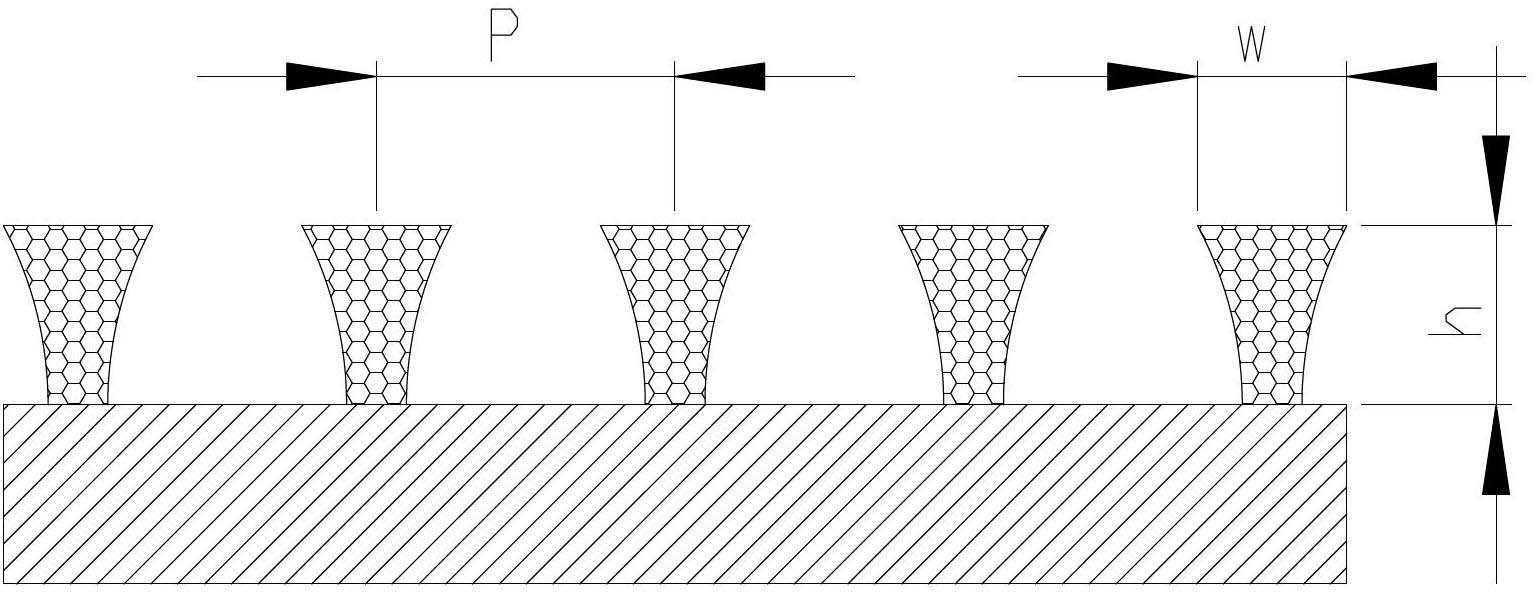
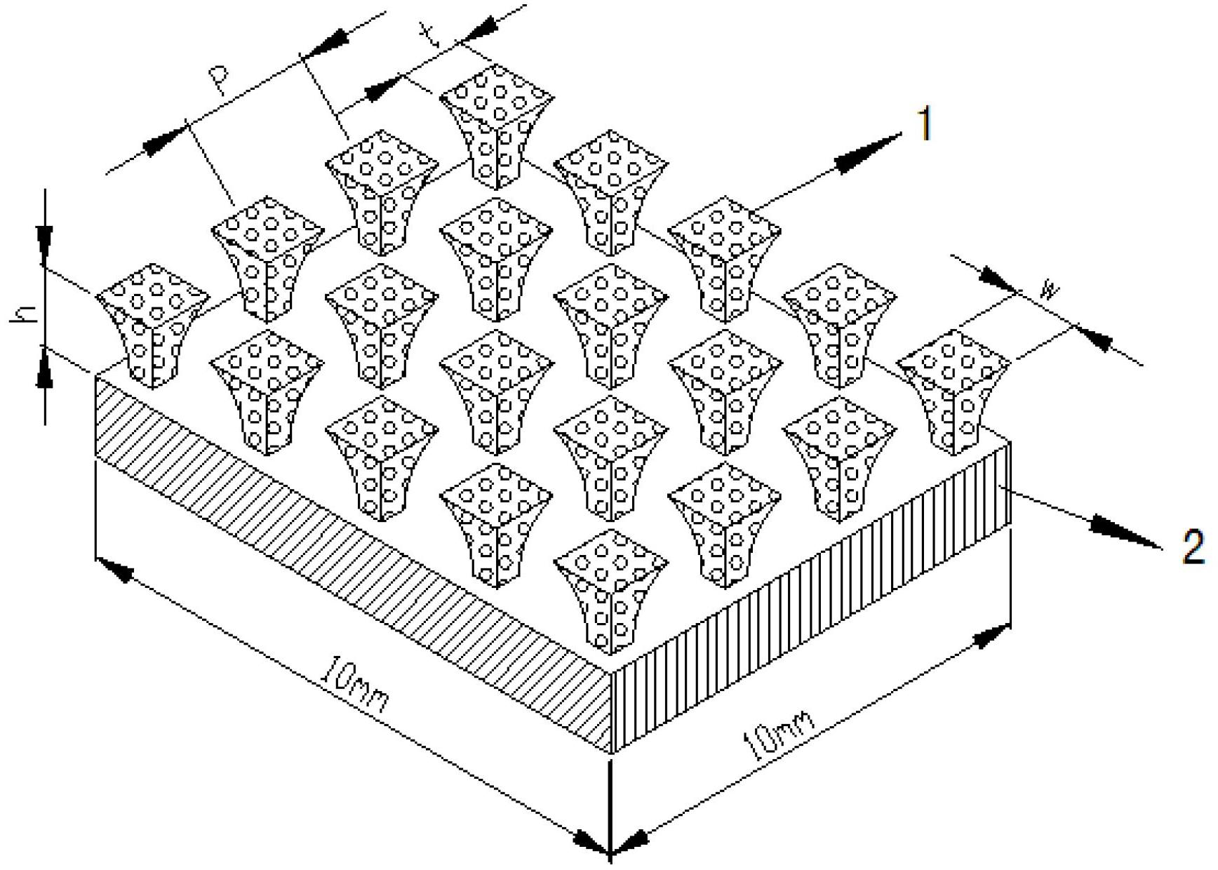
[0025] refer to figure 1 , the present invention includes a heat dissipation plate on the surface of the chip and a three-dimensional microstructure of several porous variable curvature profiles formed on the top of the heat dissipation plate 2 by using foam metal 1, wherein the upper and lower surfaces of the three-dimensional microstructure of the porous variable curvature profile are squares of different sizes, The side surfaces are arc surfaces of the same shape.

[0026]Due to the three-dimensional microstructure with curved shape, the use of traditional photolithography etching, wet etching and other technologies can no longer meet the needs. As early as 1993, a new microfabrication process was proposed by Japanese professor Ikuta (IKUTA K, HIROWATARI K, Real three dimensional micro fabrication using stereo lithography and metal molding [C], Proceeding...


PUM

PropertyMeasurementUnit
Heightaaaaaaaaaa

Abstract

The invention relates to an ultra-high heat-flow density reinforced boiling heat transfer technology, in particular to a chip reinforced boiling heat transfer structure of multi-pore microcolumn variable camber molded surfaces, which is suitable for an ultra-high heat-flow density micro-electronic chip efficiently-cooling technology. The chip reinforced boiling heat transfer structure comprises a heat radiating plate on the surface of a chip, and a plurality of multi-pore variable camber molded surface three-dimensional microstructures formed on the heat radiating plate by using foam metal, wherein the multi-pore variable camber molded surface three-dimensional microstructures are arranged in an array form and are of a six-faced shape, the upper surfaces and the lower surfaces of the multi-pore variable camber molded surface three-dimensional microstructures are squares with different sizes, and four side surfaces of the multi-pore variable camber molded surface three-dimensional microstructures are arc surfaces with same shapes. According to the chip reinforced boiling heat transfer structure, enough steam bubble nucleuses of boiling and large specific surface area as well as high heat transfer efficiency are provided, the problem of interaction of a suction function of a capillary pump and synchronous increasing or synchronous reducing of a fluid flow resistance is effectively solved, therefore, ultra-high heat-flow density nucleate boiling heat transfer is remarkably improved, thus effective heat transfer of an ultra-high critical heat-flow density micro-electronic device is ensured.

Description

technical field [0001] The invention relates to an ultra-high heat flux density boiling enhanced heat exchange technology, in particular to a high-efficiency cooling technology suitable for ultra-high heat flux density microelectronic chips, in particular to a chip enhanced boiling heat exchange structure with a porous micro-pillar variable curvature profile. Background technique [0002] With the rapid development of MEMS microelectronic machining technology, the requirements for high frequency, high speed and high integration of electronic components are getting higher and higher. The high temperature working environment will inevitably affect the performance of electronic components, which requires more Efficient cooling to meet its requirements. Therefore, effectively solving the heat dissipation problem of electronic components has become a key technology in the current electronic components and electronic equipment manufacturing. [0003] At present, the use of liquid...

Claims


Application Information

Patent Timeline
IPC IPC(8): H01L23/427
Inventor 魏进家薛艳芳
Owner XI AN JIAOTONG UNIV
Why Eureka
Try Eureka