Synchronous pulse control circuit for preventing faults of microprogrammed control unit (MCU) or driving integrated circuit (IC)

A technology for controlling circuits and synchronous pulses, applied in pulse technology, pulse processing, pulse shaping, etc., can solve problems such as complex structure, high cost, and large volume, and achieve good reliability, low cost, and good followability

Active Publication Date: 2012-09-19
浙江榆阳电子股份有限公司
View PDF4 Cites 15 Cited by
  • Summary
  • Abstract
  • Description
  • Claims
  • Application Information

AI Technical Summary

Problems solved by technology

[0013] What the present invention aims to solve is a series of related technical problems such as complex structure, high cost, large volume, and poor technical feasibility of the existing control circuit fo...

Method used


Image

  • Synchronous pulse control circuit for preventing faults of microprogrammed control unit (MCU) or driving integrated circuit (IC)
  • Synchronous pulse control circuit for preventing faults of microprogrammed control unit (MCU) or driving integrated circuit (IC)
  • Synchronous pulse control circuit for preventing faults of microprogrammed control unit (MCU) or driving integrated circuit (IC)

Examples


Embodiment 1

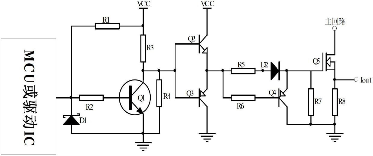
[0035] The realization scheme of the present invention is as Figure 11 The control circuit is shown in the dotted box. The synchronous pulse control circuit of the present invention includes a signal sampling circuit, a synchronous pulse conversion circuit and a shaping control signal output circuit.

[0036] The signal sampling circuit consists of an operational amplifier OPAMP1 and a peripheral circuit composed of resistors R1, R2, R3 and R4. Among them: the series circuit composed of voltage dividing resistors R2 and R3 provides a reference voltage for the negative input terminal of the operational amplifier OPAMP1; one end of the resistor R1 is connected to the output terminal of the MCU or driver IC, and the other end is connected to the positive input terminal of the operational amplifier OPAMP1; the resistor R4 One end is connected to the output end of the operational amplifier OPAMP1.

[0037] Described synchronous pulse conversion circuit comprises pulse coupling c...

Embodiment 2

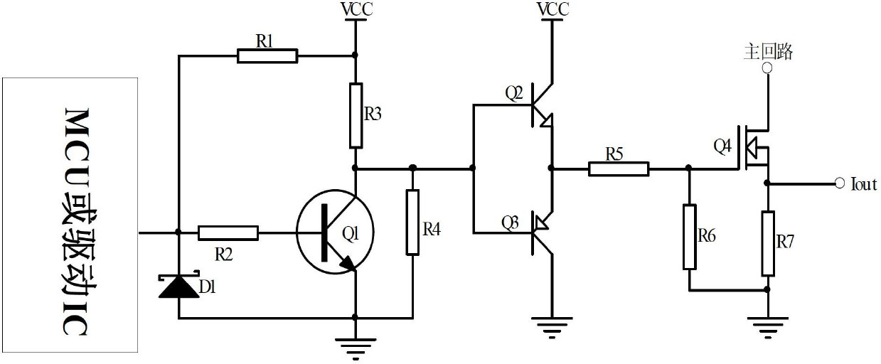
[0043] refer to Figure 12 , this example is in Figure 11 Improvements based on the examples. and Figure 11 The difference between the embodiments is that the signal sampling circuit is composed of a resistor R4, and the rest of the structures are the same as Figure 11 The embodiment is the same.

Embodiment 3

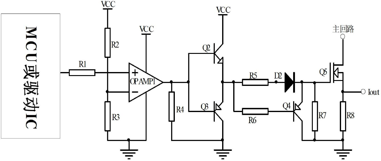
[0045] refer to Figure 13 , this example is in Figure 11 Improvements based on the examples. and Figure 11 The difference of the embodiments is that the shaping circuit adopts a first-stage RC integration circuit, which is composed of a resistor R5 and a capacitor C2, and the rest of the structures are the same as Figure 11 The embodiment is the same.


PUM


Abstract

The invention discloses a synchronous pulse control circuit for preventing faults of a microprogrammed control unit (MCU) or a driving integrated circuit (IC). The circuit comprises a signal sampling circuit, a synchronous pulse conversion circuit and a rectifying control signal output circuit. The synchronous pulse control circuit is characterized in that the sampling circuit conducts sampling and amplitude adjustment on output voltage signals of the MCU or the driving IC and outputs sampling voltage signals to the synchronous pulse conversion circuit. The synchronous pulse conversion circuit couples normal pulse sampling voltage signals controlled by duty ratio at the input end of the rectifying control signal output circuit and simultaneously stops direct current fault voltage signals. The rectifying control signals output circuit clamps the control end of a complementary push-pull type power amplification circuit of a main driving circuit at the zero potential when faults occur. The synchronous pulse control circuit technically has the advantages of being good in following performance, high in reliability and low in cost.

Description

technical field [0001] The invention relates to the field of pulse conversion control, in particular to a synchronous pulse control circuit for preventing MCU or drive IC failure. Background technique [0002] At present, the traditional electronic power switch, when the pulse drive source (MCU or drive IC) fails, the drive pulse signal width will be affected by the input stage (pre-stage) to reach the maximum value, that is, the high-level full-on operation Mode, which will make the power switch tube of the subsequent stage be in the full duty cycle conduction mode, and the power switch tube will be damaged due to excessive current. [0003] figure 1 Shown is a traditional complementary push-pull power drive circuit with triode inverting amplifying input. When the MCU or driver IC of the previous stage fails (U 0 It is all low level, normally it is a drive signal with controllable pulse width), in this traditional circuit, this fault will cause the power switch tube to e...

Claims


Application Information

Patent Timeline
IPC IPC(8): H03K5/13H03K5/01H03K17/08H03K5/134
Inventor 方洁苗李积明
Owner 浙江榆阳电子股份有限公司
Why Eureka
Try Eureka