Method and monitor for compensating video image

A technology of video image and compensation method, which is applied in the field of video processing and can solve problems such as unsatisfactory playback effects

Inactive Publication Date: 2012-09-19
SHENZHEN SKYWORTH QUNXIN SECURITY TECH
View PDF4 Cites 22 Cited by
  • Summary
  • Abstract
  • Description
  • Claims
  • Application Information

AI Technical Summary

Problems solved by technology

[0004] The embodiment of the present invention provides a video image compensation method, which aims to solve the problem that the existing video image compensation method is difficult to compensate the images in various scenes and the playback effect is not ideal

Method used


Image

  • Method and monitor for compensating video image
  • Method and monitor for compensating video image
  • Method and monitor for compensating video image

Examples


Embodiment 1

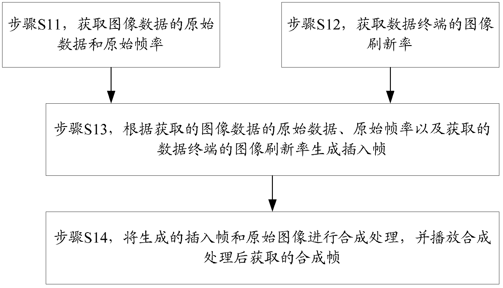
[0036] figure 1 The flow of the video image compensation method provided by the first embodiment of the present invention is shown. In this embodiment, the effect of smoothing the video is achieved by inserting an estimated image frame between two image frames, and the details are as follows:

[0037] Step S11, acquiring the original data and the original frame rate of the image data.

[0038] In this embodiment, the input image data is captured and buffered, and then the captured signal is compared point by point by using the high-speed computing capability of the CPU, so as to capture the original data and the original frame rate of the image data. Wherein, the image data includes image data before processing and image data after processing. For example, when the received image data is a low voltage differential signal (Low Voltage Differential Signaling, LVDS) that is played by the front-end player, processed by the SOC chip, and converted by the SCALER, the original frame...

Embodiment 2

[0089] Figure 5 A structure of a video image compensation monitor provided by the second embodiment of the present invention is shown, and for convenience of description, only parts related to this embodiment are shown.

[0090] The video image compensation monitor can run on a software unit, a hardware unit, or a combination of software and hardware in the terminal, and can also be integrated into these terminals as an independent pendant or run in the application systems of these terminals, wherein:

[0091] The original image parameter acquisition unit 51 is configured to acquire the original data and the original frame rate of the image data.

[0092] In this embodiment, the input image data is captured and cached, and then the cached image data is compared point by point. For example, the input LVDS signal is captured and cached, and then the LVDS signal is compared point by point using the high-speed processing capability of the CPU. , so as to capture the original dat...


PUM


Abstract

The invention is suitable for the field of processing a video and provides a method and a monitor for compensating a video image. The method comprises the steps of: obtaining primary data and primary frame rates of image data; obtaining an image refresh rate of a data terminal; generating an insert frame according to the obtained primary data and the obtained frame rates of the image data and the obtained image refresh rate of the data terminal; and carrying out synthesis processing for the generated insert frame and a primary image, and playing a synthesis frame obtained after the synthesis processing. In the embodiment of the invention, the image data of the insert frame are calculated according to an obtained motion vector of the primary data by processing the primary date without directly adopting the primary data of the image, thus the image data of the insert frame can reflect a motion trail of an object and can play a corresponding compensation role for images under various scenes, the synthesis frame comprising the insert frame can be smoothly played, and the played image processing effect can be more ideal.

Description

technical field [0001] The invention belongs to the field of video processing, in particular to a video image compensation method and a monitor. Background technique [0002] With the continuous advancement of modern display technology, people can see clearer and clearer images, but due to various technical limitations, such as data acquisition, signal codec, signal transmission and other factors, the images we watch are still There are many deficiencies, and the visual effect is not ideal enough. [0003] In order to improve the visual effect, a generation of motion compensation technology has been developed. The earliest is ordinary interlaced video, and the video image displayed by this technology has very obvious shaking and flying colors; later, 3D comb filter (3D COMB FILTER) technology appeared, which has significantly improved the quality of relatively still pictures. Improvement, but for the image of 24 frames / s video signal to be converted into a video signal for...

Claims


Application Information

Patent Timeline
Patent Type & Authority Applications(China)
IPC IPC(8): H04N7/01G09G5/393
Inventor 张鑫王宝雄苏簪斗
Owner SHENZHEN SKYWORTH QUNXIN SECURITY TECH
Why Eureka
Try Eureka