Composite steel plate shearing wall for improving stability

A technology of composite steel plate and composite plate, applied in walls, building components, buildings, etc., can solve the problems of reducing labor costs, unfavorable conditions, shortening construction time, etc., and achieve improved comfort and durability, and large shear buckling capacity , the effect of maintaining a quiet atmosphere

Inactive Publication Date: 2012-09-26
HOHAI UNIV
View PDF7 Cites 5 Cited by
  • Summary
  • Abstract
  • Description
  • Claims
  • Application Information

AI Technical Summary

Problems solved by technology

Due to the small thickness of the steel plate, the steel plate shear wall saves steel far more than the thick plate steel plate shear wall by utilizing the strength of the steel plate after buckling, but the hysteresis curve has different degrees of pinching phenomenon, and its most obvious disadvantage is: the steel plate Under the reciprocating load, the buckling direction and the diagonal tension field are constantly changing alternately, making loud, drumming noises, causing users to feel panic and anxiety, causing adverse effects on the normal use of the structure, and seriously hampering this. Promotion of an Excellent Structural Form
The above-mentioned shortcomings of the thin-plate steel plate shear wall can be improved to a certain extent by adding stiffeners and external concrete slabs to the steel plate of the thin plate steel plate shear wall, but the added stiffeners and external concrete slabs are all structural measures. At the same time, the steel plate shear wall itself does not have the functions of thermal insulation, sound insulation, and vibration isolation. labor cost

Method used


Image

  • Composite steel plate shearing wall for improving stability
  • Composite steel plate shearing wall for improving stability
  • Composite steel plate shearing wall for improving stability

Examples


Embodiment Construction

[0023] Below in conjunction with accompanying drawing, the present invention is described in further detail:

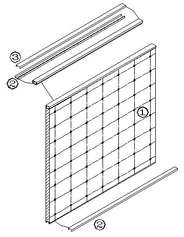
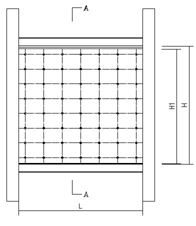
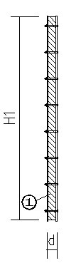
[0024] As shown in the figure: a composite steel plate shear wall with enhanced stability, including a composite plate 1 , a first channel steel connector 2 , and a second channel steel connector 3 .

[0025] The top and bottom ends of the composite panel 1 are respectively arranged with first channel steel connectors 2, and the notches of the first channel steel connectors 2 at the top and bottom ends are outward, and the notches of the second channel steel connectors 3 are arranged inward on the composite panel. On the first channel steel connector 2 at the top of the plate 1. The composite panel 1 includes two steel plates and a rigid polyurethane foam layer; a rigid polyurethane foam layer is arranged between the two steel plates; a number of screw holes are arranged on the surface of the steel plate, and bolts pass through the screw holes to connect the steel pla...


PUM

PropertyMeasurementUnit
diameteraaaaaaaaaa
tensile strengthaaaaaaaaaa
compressive strengthaaaaaaaaaa

Abstract

The invention relates to a composite steel plate shearing wall for improving stability, which belongs to a lateral force resisting component in the technical field of structural engineering and is applied to newly construction of a frame-steel plate shearing wall and reinforcement and seismic rehabilitation of a constructed steel frame structure. Each of the top end and the bottom end of a composite plate is provided with a first channel steel connector, notches of the first channel steel connectors at the top end and the bottom end are arranged outwards, and a notch of a second channel steel connector is arranged inwards on the first channel steel connector at the top end of the composite plate. According to the composite steel plate shearing wall for improving stability, the form of clamping a hard polyurethane foam plate between two steel plates remarkably is adopted so as to increase the plane external stiffness of the cross section of the plate so that the steel plate shearing wall obtains great anti-shearing buckling bearing capacity to avoid entire buckling of the structure under the action of a larger horizontal load; and meanwhile, the steel plate is divided into small areas by dense bolts and is closely combined with the hard polyurethane foam plate to prevent partial buckling of the steel plate.

Description

technical field [0001] The invention relates to a composite steel plate shear wall with enhanced stability, which belongs to the lateral force-resistant member in the technical field of structural engineering, and is suitable for reinforcement or post-earthquake repair of new frame-steel plate shear wall projects and existing steel frame structures. Background technique [0002] Earthquake is the biggest natural enemy of building structure, and the steel plate shear wall structure has been paid more and more attention by researchers because of its good seismic performance. Engineering practice, scientific research and post-earthquake investigations in the past 30 years have fully proved that the steel plate shear wall structure has excellent large deformation capacity, good plastic performance, and stable hysteretic performance, and is suitable for use as a structural form of high-rise buildings in earthquake areas. [0003] The steel plate shear wall structure is divided in...

Claims


Application Information

Patent Timeline
Patent Type & Authority Applications(China)
IPC IPC(8): E04B2/56
Inventor 齐永胜米旭峰刘卫云李东周泓代国忠李卫青骆勇军张智超刘平
Owner HOHAI UNIV
Why Eureka
Try Eureka