Catalytic cracking cold-hot catalyst pre-lifter
A catalytic cracking and cold catalyst technology, applied in the field of catalytic cracking cold and hot catalyst pre-lifters, can solve the problems of catalyst hydrothermal deactivation, poor device operation stability, long particle residence time distribution, etc.
- Summary
- Abstract
- Description
- Claims
- Application Information
AI Technical Summary
Problems solved by technology
Method used
Image

Examples
Embodiment 1
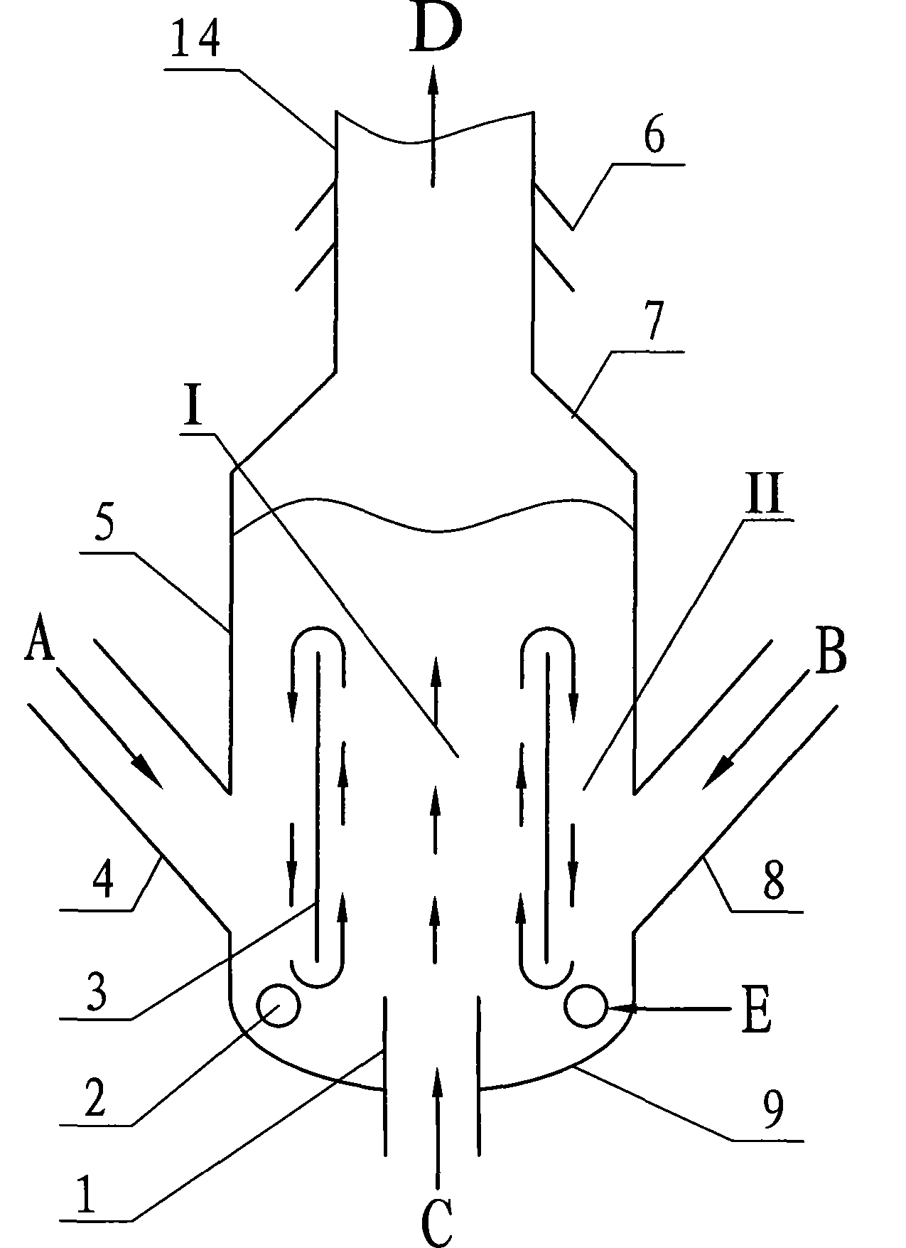
[0029] figure 1 A typical form of the cold and hot catalyst pre-lifter of the present invention is given, such as figure 1 As shown, the cold and hot catalyst pre-lifter includes a section of pre-lifting cylinder (5) with a diameter of 1.2 to 3 times the diameter of the riser reactor (14), the height of which is 1 to 2 times the diameter, and the riser reactor (14) is connected by a cone section (7), and a head (9) is arranged at the bottom. The pre-lifting cylinder is provided with a concentric circular guide cylinder (3), so that the pre-lifting cylinder is divided into two connected areas, an inner ring (I) and an outer ring (II). The ratio of the diameter of the deflector cylinder (3) to the diameter of the pre-lift cylinder (5) is 0.5-0.9. The height is 0.5 to 1.8 times the diameter of the pre-lifting cylinder (5). A hot catalyst feed pipe (4) and a cold catalyst feed pipe (8) are arranged circumferentially on the pre-lifting cylinder (5). The catalyst feed pipes are loca...
Embodiment 2
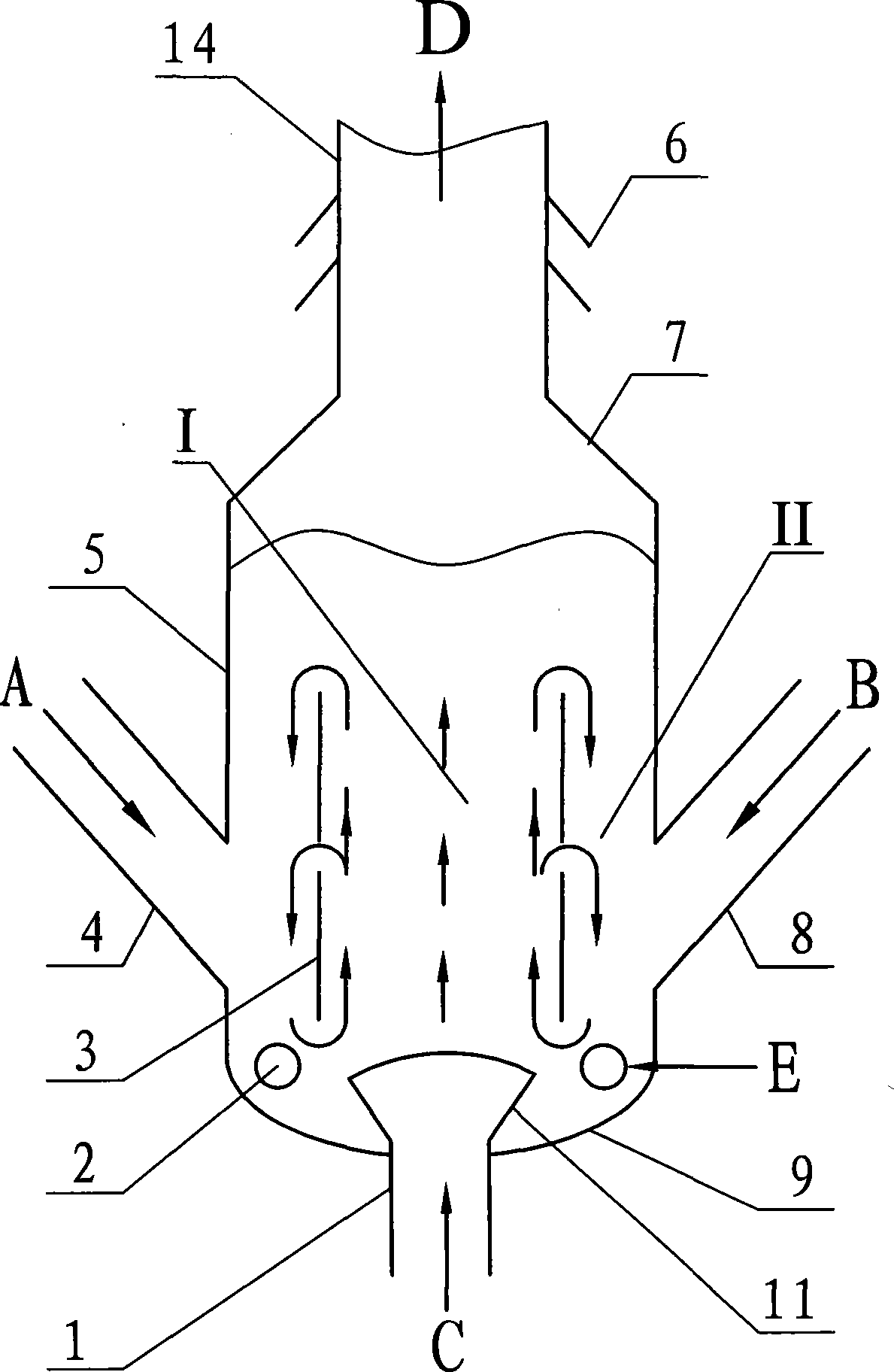
[0031] figure 2 Another typical form of the cold and hot catalyst pre-lifter of the present invention is given, and figure 1 The difference in the structure shown is that a diversion tube (3) of a different structure is used, and in addition, a different main pre-lifting air (C) introduction structure is used. Such as figure 2 As shown, the guide tube (3) is divided into two upper and lower sections along the height direction, with an annular gap in the middle. The height of the guide tube (3) including the annular gap is 0.5 to 1.8 of the diameter of the pre-lifting cylinder (5) Times. The existence of the annular gap will change the internal circulation flow pattern of the particles, such as figure 2 As indicated by the middle arrow, the lateral mixing of particles can be further enhanced. Another difference is that a shower head type gas distributor (11) is installed at the end of the main pre-lifting air pipe (1), so that the main pre-lifting air (C) can be more evenly i...
Embodiment 3
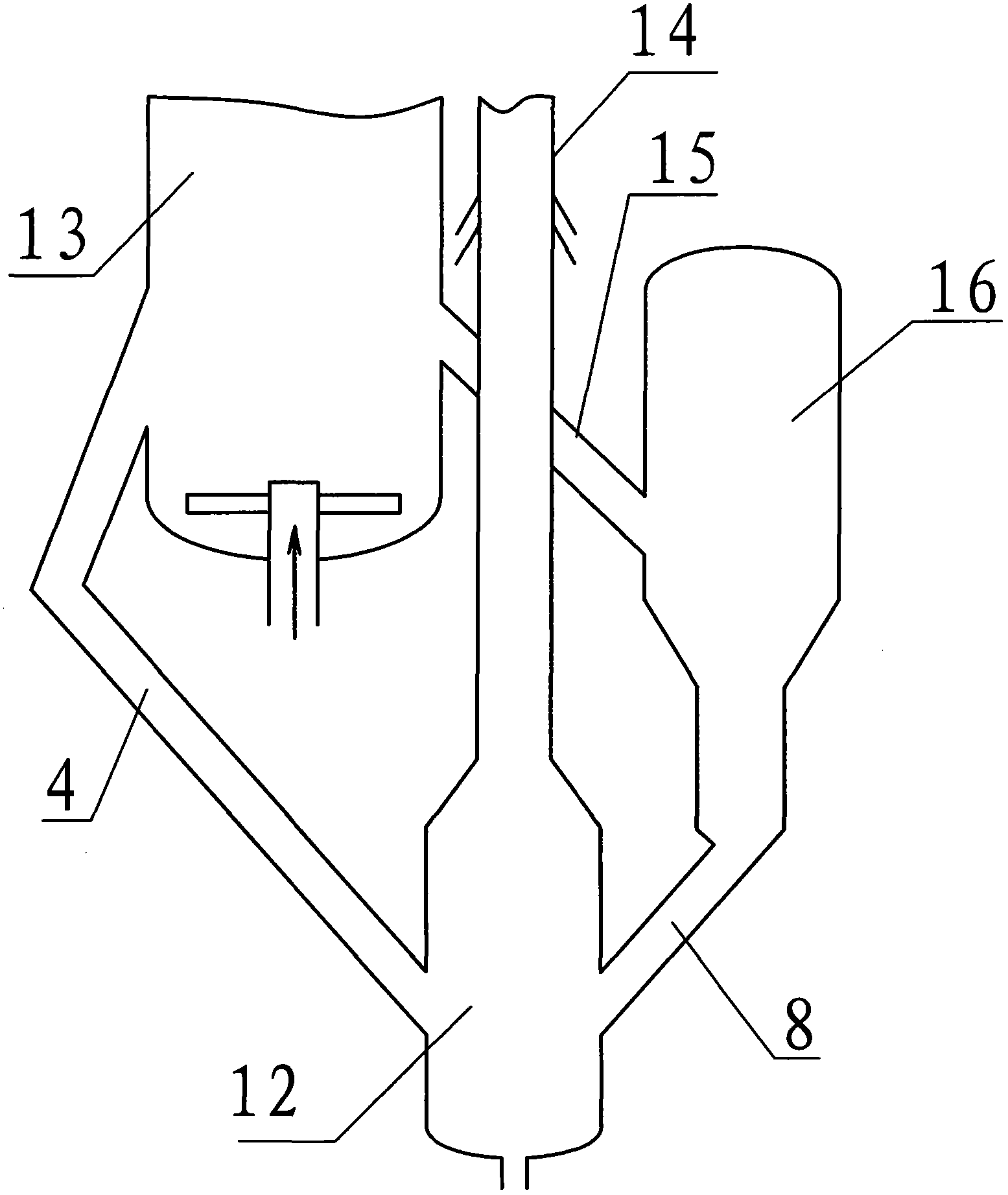
[0033] See image 3 This embodiment is a method of using the pre-riser of the present invention in a catalytic cracking unit. The pre-lifter (12) is any pre-lifter structure included in the present invention, such as the structure described in the first embodiment or the second embodiment. Such as image 3 As shown, two strands of regenerated catalyst are drawn from the regenerator (13), one strand enters the pre-elevator (12) through the hot catalyst feed pipe (4) as the hot catalyst feed, and the other strand is introduced through the inclined pipe (15) To the catalyst cooler (16) for cooling to reduce the temperature of the catalyst, as the cold catalyst feed, enter the pre-lifter (12) through the cold catalyst feed pipe (8), and enter the riser reactor (14) after mixing with the hot catalyst ). This embodiment can obtain a larger catalyst-to-oil ratio without affecting the performance of the regeneration system, which is beneficial to increase the number of catalyst acti...
PUM
 Abstract
Description
Claims
Application Information
 - R&D
- Intellectual Property
- Life Sciences
- Materials
- Tech Scout
- Unparalleled Data Quality
- Higher Quality Content
- 60% Fewer Hallucinations
Browse by: Latest US Patents, China's latest patents, Technical Efficacy Thesaurus, Application Domain, Technology Topic, Popular Technical Reports.
© 2025 PatSnap. All rights reserved.Legal|Privacy policy|Modern Slavery Act Transparency Statement|Sitemap|About US| Contact US: help@patsnap.com