Vehicle braking energy recovery system

A technology of energy recovery and vehicle braking, which is applied in the direction of brakes, vehicle components, brake transmissions, etc., can solve the problems of high cost, high manufacturing process requirements, complex structure, etc., to ensure stability and extend driving mileage , The effect of recovering braking energy

Inactive Publication Date: 2012-10-03
TSINGHUA UNIV
6 Cites 24 Cited by

AI-Extracted Technical Summary

Problems solved by technology

Toyota-Prius brake system and Continental-Hybrid brake system represent the frontier of the development of brake feedback function. However, the above two existing brake systems are a...

Abstract

The invention relates to a vehicle braking energy recovery system which comprises a vehicle hydraulic braking system and a vehicle stability control system hydraulic unit, wherein an oil path between each bypass of electromagnetic valve and an oil pump motor is respectively provided with a pedal stroke simulator so as to form a hydraulic control unit; each oil inlet of each hydraulic control unit is respectively connected with each oil outlet of a brake master cylinder through an oil inlet pipeline; each oil inlet pipeline is provided with a master cylinder pressure sensor; each oil outlet of each hydraulic control unit is respectively and correspondingly connected with a brake wheel cylinder through an oil outlet pipeline; an oil outlet pipeline between the oil outlet of each front wheel and a corresponding front wheel brake wheel cylinder is provided with a front wheel cylinder pressure sensor; the master cylinder pressure sensors and the front wheel cylinder pressure sensors collect pressure signals and send the pressure signals to a brake controller; and under a control mode, the brake controller and an entire vehicle controller perform CAN (Controller Area Network) communication; and the entire vehicle controller simultaneously performs CAN communication together with a motor controller so as to control a driving motor to brake. The vehicle braking energy recovery system can be widely applicable to pure electric vehicles or hybrid electric vehicles.

Application Domain

Fluid braking transmission

Technology Topic

Electric machineryControl mode +16

Image

  • Vehicle braking energy recovery system
  • Vehicle braking energy recovery system

Examples

  • Experimental program(1)

Example Embodiment

[0013] The present invention will be described in detail below with reference to the drawings and embodiments.
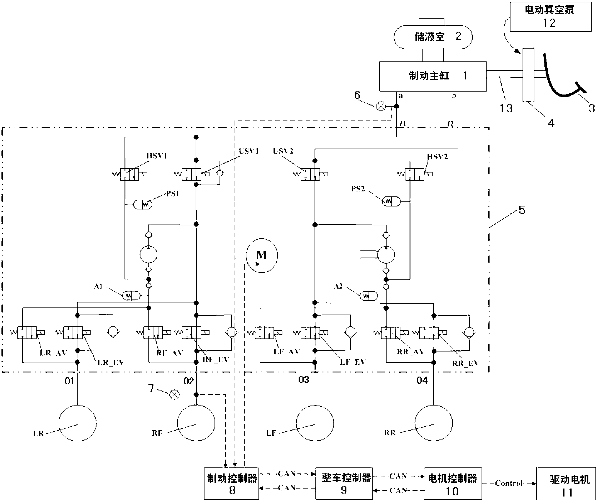
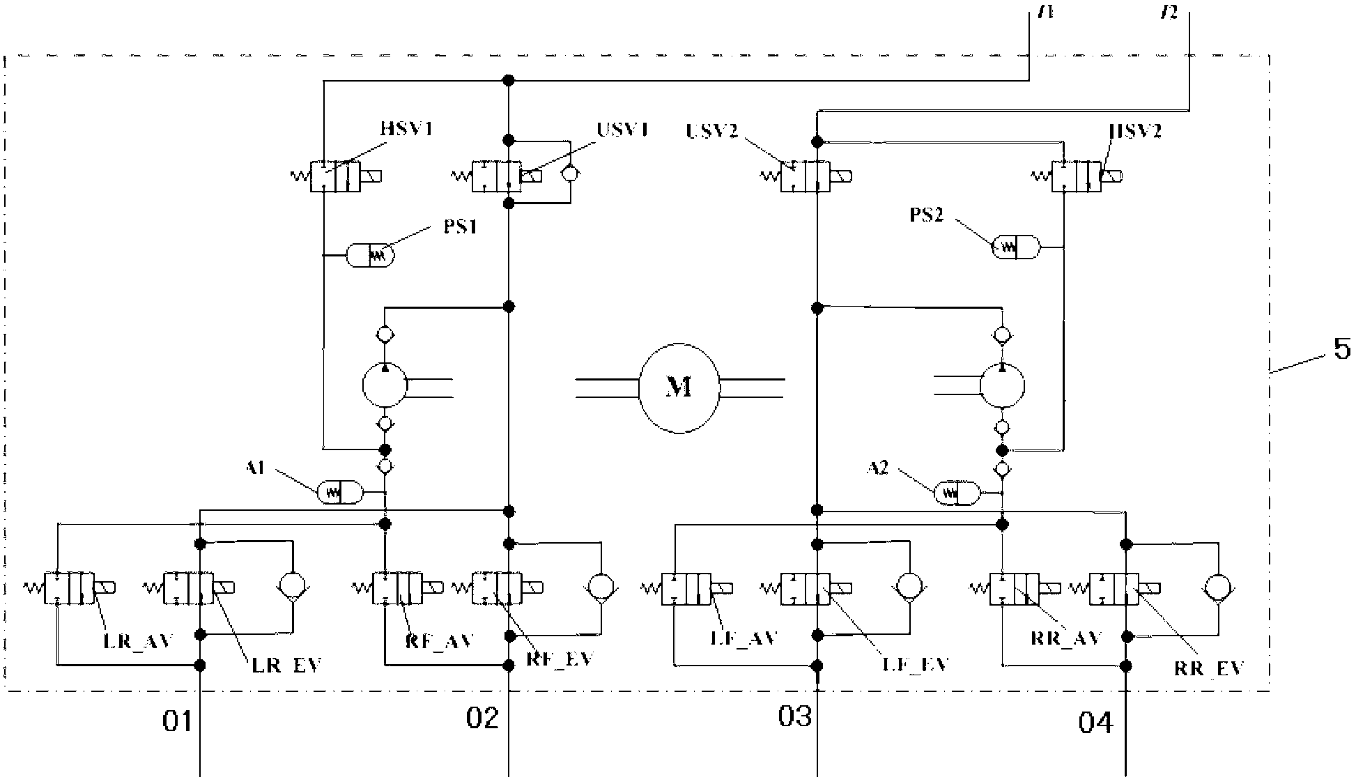
[0014] Such as figure 1 , figure 2 As shown, the present invention is an improvement on the basis of the existing vehicle traditional hydraulic brake system and vehicle stability control system hydraulic unit. The vehicle traditional hydraulic brake system includes a master cylinder 1, a reservoir 2, a brake Power pedal 3, vacuum booster 4 and four wheel brake cylinders LR, RF, LF, RR; the hydraulic unit of the vehicle stability control system includes the right front-left rear brake oil circuit and the left front-right rear brake oil circuit, Each brake oil circuit is equipped with main circuit solenoid valves USV1, USV2, bypass solenoid valves HSV1, HSV2, oil inlet and outlet solenoid valves of each wheel, oil pump, oil pump motor and low-pressure accumulator, right front-left rear brake oil Road and left front-right rear brake oil circuit share a pumping motor M, where the wheel inlet valve includes left rear wheel inlet valve LR_AV, right front wheel inlet valve RF_AV, left front wheel inlet valve LF_AV and right rear wheel The oil inlet valve RR_AV and the wheel oil outlet valve include the left rear wheel oil outlet valve LR_EV, the right front wheel oil outlet valve RF_EV, the left front wheel oil outlet valve LF_EV and the right rear wheel oil outlet valve RR_EV.
[0015] The feature of the present invention is that a pedal stroke simulator PS1 or PS2 is provided on the oil path between each bypass solenoid valve of the hydraulic unit of the vehicle stability control system and the pumping motor to form a hydraulic control unit 5 with braking energy recovery function. ; Each oil inlet I1, I2 of the hydraulic control unit 5 is respectively connected to each oil outlet a, b of the brake master cylinder 1 through the oil inlet pipe, and any oil inlet pipe is provided with a master cylinder pressure sensor 6, Used to collect the pressure value of the brake master cylinder 1; each oil outlet 01, 02, 03 or 04 of the hydraulic control unit 5 is connected to each wheel brake cylinder through the oil outlet pipe, and any front wheel discharges oil A front wheel cylinder pressure sensor 7 is provided on the oil outlet pipe between the port and the corresponding front wheel cylinder to collect the pressure value of the front wheel cylinder. The master cylinder pressure sensor 6 and the front wheel cylinder pressure sensor 7 respectively collect pressure signals and send them to the brake controller (BCU) 8. The brake controller 8 controls the solenoid valves, pedal stroke simulator, and oil pump according to the pressure signals. It works with the pumping motor, and carries out CAN communication with the vehicle controller (VCU) 9 at the same time, and the vehicle controller 9 carries out CAN communication with the motor controller (MCU) 10 at the same time to control the driving motor 11 for braking.
[0016] In the above embodiment, the present invention further includes an electric vacuum pump 12, wherein the master cylinder 1 is connected to the brake pedal 3 through a master cylinder push rod 13, and a vacuum booster is provided between the master cylinder push rod 13 and the brake pedal 3. The electric vacuum pump 12 is connected to the vacuum booster 4 to provide brake boosting. For the hydraulic braking system of pure electric vehicles, the electric vacuum pump 12 is always working; for the hydraulic braking system of hybrid electric vehicles, if the engine is in working state (including idling state), the electric vacuum pump 13 does not need to work, otherwise the electric vacuum pump 12 needs to be always working jobs.
[0017] Such as figure 1 , figure 2 As shown, the following specific examples further illustrate the working mode of the brake energy recovery system of the present invention: the brake controller 8 monitors the wheel speed signals of the wheels in real time, and exchanges information with the vehicle controller 9 through the CAN bus , And according to the acquired signal and vehicle information, determine the current control mode that should be entered. The brake controller 8 includes five control modes: brake energy feedback control mode, ABS control mode, brake energy recovery and ABS integration Control mode, ASR control mode and ESP control mode. Since the electric drive vehicle is generally front-wheel drive, the following electric drive vehicle with front-wheel drive is an embodiment to further illustrate the working process of each control mode.
[0018] 1. Braking energy feedback control mode
[0019] 1) The vehicle controller 9 monitors the real-time operating status of the vehicle (including status information such as power battery, drive motor and vehicle speed), calculates the maximum feedback torque value M0 currently provided by the drive motor 11, and passes the maximum feedback torque value M0 through CAN The bus is sent to the brake controller 8.
[0020] 2) The master cylinder pressure sensor 6 and the front wheel cylinder pressure sensor 7 respectively monitor the pressure value P1 of the brake master cylinder and the front wheel cylinder pressure value P2, and send the above two pressure values ​​to the brake controller 8 respectively.
[0021] 3) The brake controller 8 calculates the master cylinder pressure change rate dP1/dt according to the master cylinder pressure value P1, combined with the maximum feedback torque value M0 currently provided by the drive motor, the master cylinder pressure value P1 and the front wheel cylinder pressure value P2, calculate the motor feedback braking torque command value M1 that should be applied to the front axle, and send it to the vehicle controller 9 through the CAN bus. The vehicle controller 9 sends the motor feedback braking torque command value M1 through the CAN bus It is sent to the motor controller 10, and the motor controller 10 sends the actual feedback torque value M2 currently sent by the driving motor 11 to the brake controller 8 via the vehicle controller 9 through the CAN bus.
[0022] 4) Such as figure 2 As shown, the brake controller 8 compares the motor feedback braking torque command value M1 with the current actual feedback torque value M2 of the drive motor, assuming M3=M1-M2; when M3 is equal to zero, the brake controller 8 controls the hydraulic pressure Unit 5 sends out the front wheel pressure holding command, that is, the right front wheel inlet valve RF_EV and the left front wheel inlet valve LF_EV are energized and closed to realize the pressure maintenance of the two front wheel cylinders. When M3 is greater than zero, the brake controller 8 sends a front wheel pressurization command to the hydraulic control unit 5. That is, the brake controller 8 calculates the oil pump motor M, the left front wheel inlet valve LF_EV and the left front wheel inlet valve according to the size of M3. The duty cycle command of the right front wheel inlet valve RF_EV is sent to the hydraulic control unit 5. The pumping motor pumps the brake fluid stored in the pedal stroke simulator into the front wheel cylinder, so that the front wheel The pressure of the cylinder increases, and at the same time, the left front wheel inlet valve LF_EV and the right front wheel inlet valve RF_EV work in the pulse width modulation state, so that the control of different boost rates can be realized. When M3 is less than zero, the brake controller 8 sends a front wheel decompression command to the hydraulic control unit 5, that is, the right front wheel inlet valve RF_EV and the left front wheel inlet valve LF_EV are energized and closed, and the brake controller 8 according to M3 Calculate the duty ratio commands of the oil pump motor M, the left front wheel oil outlet valve LF_AV and the right front wheel oil valve RF_AV respectively, and send them to the hydraulic control unit 5. The oil pump motor will The brake fluid is pumped out and stored in the low-pressure accumulators A1 and A2, so that the pressure of the front wheel cylinders is reduced. The left front wheel oil outlet valve LF_AV and the right front wheel oil outlet valve RF_AV work under pulse width modulation. So as to realize the control of different decompression rate.
[0023] When the vehicle speed drops to a certain value, the rotational speed of the drive motor 11 will drop to a certain lower value, and the feedback torque provided by the drive motor will rapidly decrease (this is determined by the characteristics of the drive motor). 9 After monitoring this situation, immediately send a signal to the brake controller 8 and the motor controller 10 to exit the braking energy feedback control mode. The motor controller 10 controls the drive motor to quickly reduce the feedback torque to zero, and the brake controller 8 resets all The solenoid valve and the pump oil motor restore the hydraulic brake.
[0024] To sum up, in the braking energy feedback control mode, when the driver depresses the brake pedal 3, the main solenoid valves USV1 and USV2 are energized and closed and enter a non-conducting state, and the bypass solenoid valves HSV1 and HSV2 are energized and opened , Enter the conducting state, the left front wheel inlet valve LF_EV and the right front wheel inlet valve RF_EV are energized and closed, and enter the non-conducting state. At this time, the brake fluid flowing from the master cylinder 1 enters the rear wheel cylinders LR and RR, while the brake fluid that should have entered the front wheel cylinders RF and LF enters the pedal stroke simulator PS1 and PS2 respectively and is stored in Among them, the pedal feel of the driver is guaranteed.
[0025] 2. ABS control mode
[0026] When the brake controller 8 detects that there is a wheel lock tendency, assuming that the wheel is the left front wheel, at this time, the pump motor is energized, the left front wheel inlet valve LF_EV is energized and closed, and the left front wheel outlet valve LF_AV is energized and opened , The brake fluid in the left front wheel cylinder LF is pumped back to the low-pressure accumulator A2 and the main oil circuit (the pipeline of the entire brake system between the brake master cylinder and the wheel cylinder) to realize the reduction of the left front wheel Pressure control; when the brake controller 8 detects that the left front wheel lock trend disappears, the left front wheel inlet valve LF-EV and the left front wheel outlet valve LF-AV are reset at the same time, due to the lower brake pressure of the main oil circuit High, the brake pressure of the left front wheel cylinder is small, and the brake fluid will enter the left front wheel cylinder instantaneously to realize the pressure control of the left front wheel; in the ABS control mode, pressure holding control is sometimes required to enter the oil The solenoid valve is energized and closed to achieve pressure holding control.
[0027] 3. Integrated control mode of braking energy recovery and ABS
[0028] There are two control methods for this control mode, namely:
[0029] 1) When the ABS enters control, the feedback braking is immediately exited
[0030] When the brake controller 8 detects that ABS control is required, the brake controller 8 communicates with the vehicle controller 9 through the CAN bus to notify the vehicle controller 9 to enter the ABS control mode, and the vehicle controller 8 informs the motor controller 10 Immediately reduce the feedback braking torque of the drive motor 11 to zero, and exit the braking energy feedback control mode; when the ABS control exits, the brake controller 8 informs the vehicle controller 9 to resume the braking energy feedback control mode and send The current motor feedback braking torque command value that should be applied to the wheels, the vehicle controller 9 informs the motor controller 10, and the motor controller 10 controls the driving motor 11 to load the motor feedback braking torque command value, using the above-mentioned braking energy feedback control In the control method of the mode, the brake controller 8, the vehicle controller 9 and the motor controller 10 jointly realize feedback braking.
[0031] 2) When ABS enters control, feedback braking force participates in ABS control
[0032] When the brake controller 8 detects that ABS control is required, the brake controller 8 communicates with the vehicle controller 9 through the CAN bus, and the brake controller 8 informs the vehicle controller 9 to immediately enter the ABS control, and the vehicle control The motor controller 9 informs the motor controller 10 to immediately enter the ABS control, the brake controller 8 adjusts the hydraulic braking force according to the corresponding control strategy to achieve ABS control, and the motor controller 10 adjusts the feedback braking force of the drive motor 11 according to the corresponding control strategy to achieve ABS When the ABS control exits, the brake controller 8 informs the vehicle controller 9 to resume regenerative braking. Using the above-mentioned control method in the brake energy feedback control mode, the brake controller 8, the vehicle controller 9 and the motor The controller 10 jointly implements feedback braking, wherein the corresponding control strategy can adopt existing control methods such as logic thresholds, which will not be repeated here.
[0033] 4. ASR control mode
[0034] ASR is called drive anti-skid control, also often called TCS. When the vehicle is running on a low-attachment road, when the driver slams on the accelerator pedal, the drive wheels will slip and enter the ASR control mode. The ASR control mode can reduce the degree of slippage by applying braking to the pulley. The specific process of the ASR control mode is: when a certain driving wheel slips, take the right front wheel as an example, the brake controller 8 Send a control command to the hydraulic control unit 5. The main solenoid valve USV1 is energized and closed to enter the non-conducting state, the bypass solenoid valve HSV1 is energized and opened to enter the conducting state, the oil pump motor works, and the brake fluid is pumped into the right front wheel cylinder , So as to realize the pressurization control of the right front wheel; when the right front wheel is reduced to a certain extent, the main solenoid valve USV1 will enter the conducting state, the bypass solenoid valve HSV1 will enter the non-conducting state, and the right front The wheel inlet valve LF_EV is energized and closed and is in a non-conducting state. The right front wheel outlet valve RF_AV is energized and enters the conducting state. The pumping motor works and pumps the brake fluid in the right front wheel cylinder into the low-pressure accumulator A1. Thus, the pressure reduction control of the right front wheel is realized; the pressure holding control of the right front wheel is similar to that of ABS, which can be realized by energizing and closing the fuel inlet valve LF_EV of the right front wheel.
[0035] 5. ESP control mode
[0036] When the vehicle is running, when the brake controller 8 detects that the vehicle has a tendency to skid or flick, the brake controller 8 sends a control command to the hydraulic control unit 5 to perform braking control on a certain wheel to avoid sideslip or throw Tail trend. Since the working process of the ESP control mode is realized by combining the above-mentioned ABS and ASR control processes, it can be known from the working process analysis of the above-mentioned ABS and ASR that the present invention can completely realize ESP control.
[0037] The above-mentioned embodiments are only used to illustrate the present invention, and the structure and connection mode of each component can be changed. Any equivalent changes and improvements made on the basis of the technical solution of the present invention should not be excluded from the present invention. Outside the scope of protection of the invention.

PUM

no PUM

Description & Claims & Application Information

We can also present the details of the Description, Claims and Application information to help users get a comprehensive understanding of the technical details of the patent, such as background art, summary of invention, brief description of drawings, description of embodiments, and other original content. On the other hand, users can also determine the specific scope of protection of the technology through the list of claims; as well as understand the changes in the life cycle of the technology with the presentation of the patent timeline. Login to view more.

Similar technology patents

Turning gradient control valve

InactiveCN102410270ASmooth oil flow switchingGuaranteed stability
Owner:LANZHOU UNIVERSITY OF TECHNOLOGY

Pixel circuit and driving method thereof, electroluminescent display panel and display device

ActiveCN108335668AAvoid voltage instabilityGuaranteed stability
Owner:HEFEI XINSHENG OPTOELECTRONICS TECH CO LTD +1

Classification and recommendation of technical efficacy words

  • Guaranteed stability

A ccd-type colloidal gold immunochromatographic diagnostic test paper quantitative analysis system

InactiveCN102279263AGuaranteed stabilityAddressing Subjective Bias
Owner:杭州顿力医疗器械有限公司

General clamp for abrasive flow polishing of complicated hole surface

InactiveCN104551985AContinuous and stable flowGuaranteed stability
Owner:CHANGCHUN UNIV OF SCI & TECH

Laminated intelligent shock-isolation bearing capable of self-adaptively regulating cutting performance

InactiveCN101586641AGuaranteed stabilityThe interlayer displacement of the isolation layer is small
Owner:WUHAN UNIV OF TECH
Why Eureka
Try Eureka