Wind-power air compressor

An air compressor and wind power technology, which is applied in the field of horizontal drive wind turbines and wind energy and gas production, can solve the problems of increasing the friction between the piston and the cylinder, increasing the operating load of the convex teeth, and occupying a large space, so as to improve the operation efficiency, Improved discharge pressure and simple structure

Inactive Publication Date: 2012-10-03
新泰市风龙王设备有限公司
View PDF7 Cites 5 Cited by
  • Summary
  • Abstract
  • Description
  • Claims
  • Application Information

AI Technical Summary

Problems solved by technology

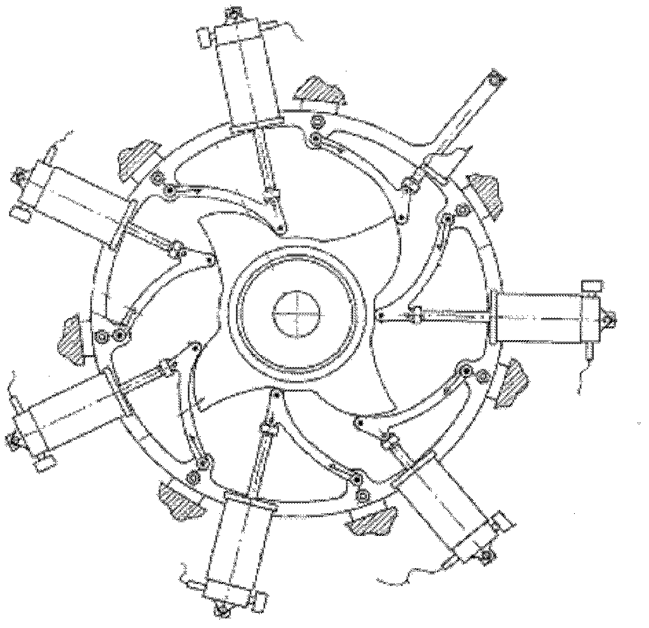
[0006] 2) The stability of the piston connecting rod is poor. The end of the piston connecting rod is fixedly connected with the swing rod through a hinge. The friction force of the body increases, thereby increasing the load when the convex teeth are running
[0007] 3) There is no device to reduce the running load of the convex teeth. When the wind speed is small, it is difficult for the wind speed to overcome the load applied to the convex teeth, so that all cylinders enter the working state, resulting in difficulty in starting
[0008] 4) The convex teeth on the power shaft mainly rely on the outer convex surface to do work on the cylinder during the whole process of movement and power transmission, while the inner concave surface on the cam does not do work on the cylinder. For a single cylinder, the cam sometimes does work on the cylinder and sometimes does not. The cylinder performs work, so the force on the entire power shaft is uneven. To ensure the uniform rotation of the power shaft, it is necessary to make the cam on the power shaft perform work on the cylinder smoothly, which puts forward higher requirements for the distribution of the cylinders. If the force on the power shaft is not uniform, the speed of the power shaft will be fast and slow, which will affect the service life of the return spring and the power shaft
[0009] 5) During the whole working process of the cylinder, it mainly relies on the return spring of the swing rod to reset, so the requirements for the spring are relatively high. The phenomenon of fatigue fracture occurs. If one of the return springs of the swing rod is not reset in time, it will cause the convex teeth to continuously hit the piston rod, resulting in noise. Due to the uneven force of the power shaft, it will further aggravate the damage of the return springs of the other swing rods. If it is damaged, the air pressure of the exhaust pipe on the cylinder will be insufficient. In severe cases, the power shaft will be stuck or the convex teeth will be damaged, so that the entire air compressor cannot work normally; Corresponding cylinder does not work properly
[0011] In this patent document, the cylinders are evenly distributed along the circumference of the entire bracket, and the cylinders placed at the lower part of the bracket are inverted. Such an arrangement will cause lubricating oil to be pressed into the exhaust pipe
[0012] 7) There are many components installed in the bracket, and it occupies a large space. The number of bracket cylinders with the same volume is less, and the air pressure provided by it is smaller when the speed of the power shaft is not changed. , if you need to provide a larger air pressure, you need to replace the bracket with a larger diameter
[0016] 1) With this cam structure, when the drive shaft rotates once, the cylinder only performs one exhaust and one suction process, which cannot realize the speed-up of the air compressor
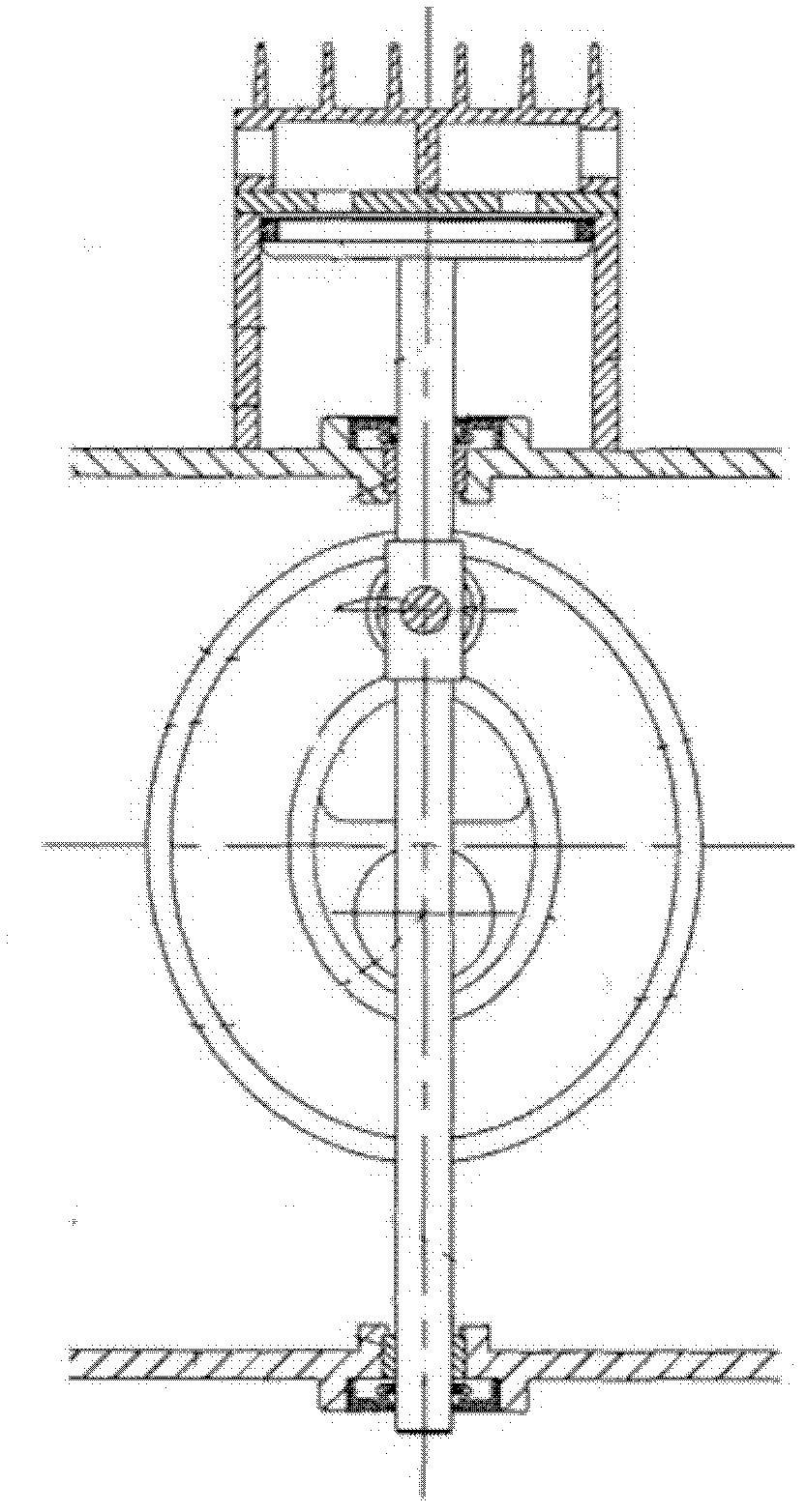
[0017] 2) If the above-mentioned patent adopts a guiding structure to guide the piston connecting rod, the stability of the piston connecting rod will be worse, because the guiding structure in the above-mentioned patent not only plays the role of guiding, but also plays the role of oil seal, because the oil seal is Elastic parts, so the piston connecting rod will swing when it moves. In order to better stabilize the piston connecting rod, the inventor added a guiding structure. Although the stability is better, new problems have also appeared. The two guiding structures The generated friction becomes larger, which increases the load on the cam during operation, which in turn affects the starting speed and the pressure of the compressed gas.
[0018] 3) From a structural point of view, this patent drives at most two cylinders to run; in addition, the guiding structure is slidingly connected with the piston connecting rod. When the piston connecting rod moves up and down, the cam also has to overcome the gap between the piston connecting rod and the upper and lower guiding structures. The generated frictional force does work. After a long time of use, one side of the guide structure wears more, and the piston connecting rod tends to tilt when it moves, which will increase the frictional force between the piston and the cylinder, so that the cam can overcome more Large frictional force does work. Under the same wind speed, the pressure of the discharged compressed gas will be reduced, and the service life of the piston will be affected at the same time.
One end of the cylinder is in the form of closed piston movement, and the negative pressure generated by it cannot be relieved. The commonly used compressor is a crankshaft of a main shaft to drive multiple cylinders to work. This invention has changed from the usual simplicity to the complexity.

Method used


Image

  • Wind-power air compressor
  • Wind-power air compressor
  • Wind-power air compressor

Examples


Embodiment Construction

[0090] In order to make the object, technical solution and advantages of the present invention clearer, the implementation manner of the present invention will be further described in detail below in conjunction with the accompanying drawings.

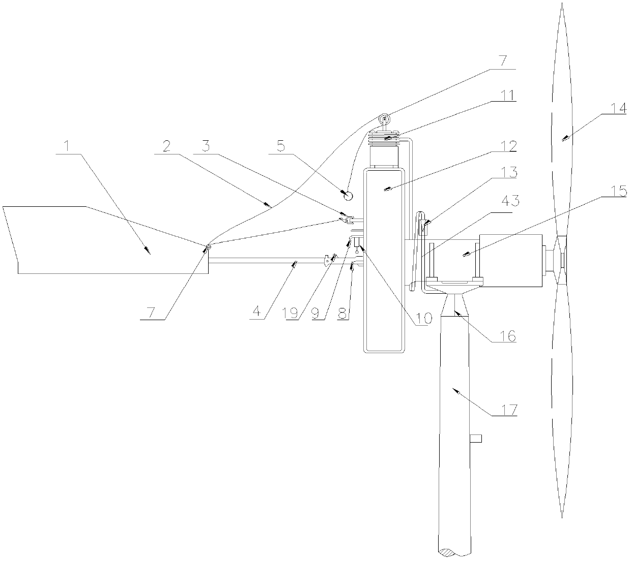
[0091] Such as image 3 Shown is a schematic diagram of the overall structure of the present invention.

[0092] A wind-powered air compressor shown in the figure mainly includes: a wind-driven transmission system, a steering shaft seat, an air compressor, an air storage chamber and an empennage lock device.

[0093] Wherein the wind power transmission system includes: fan blade 14, drive shaft 30, fan blade shaft seat 15 and empennage 1, drive shaft runs through fan blade shaft seat 15 and is fixedly connected with the drive wheel in air compressor casing 12, and empennage 1 passes through The empennage connecting rod 4 is fixed on one side of the air compressor casing 12, the empennage connecting rod is hinged with the casing 12, an...


PUM


Abstract

The invention discloses a wind-power air compressor which comprises a wind-power transmission system and an air compressor body. The wind-power transmission system comprises a driving shaft. The air compressor body comprises a box, a driving wheel and an air cylinder, wherein the air cylinder is arranged on the box, the driving wheel is arranged in the box and fixed sleeved on the driving shaft, a closed sliding rail structure is formed on a driving surface of the driving wheel, a functioning end of a piston connecting rod of the air cylinder is restrained by the sliding rail structure of the driving wheel and slides along the sliding rail, and compressed air generated by the air cylinder is transmitted to an air storage room via an air exhaust manifold. A connecting rod guiding mechanism is arranged along the axial direction of the piston connecting rod of the air cylinder and connected with a piston connecting rod roll. Extra load to the air compressor during running can be reduced, compressed air with higher pressure can be output by the air compressor at the same wind speed, stable accelerating operation of the air compressor body is realized, and noise during operation is reduced.

Description

technical field [0001] The invention relates to the field of wind energy gas collection, in particular to a wind-powered air compressor, which is mainly used in the technical field of horizontally driven wind-driven machines. Background technique [0002] The wind air compressor uses wind energy to collect gas, and converts the collected air power into gas pressure, and then stores the gas pressure and applies it to subsequent equipment. [0003] Chinese patent document CN2784610 discloses a wind-powered air compressor, which includes a fan mounting seat mounted on a bracket through a shaft, a fan blade and an empennage are arranged on the fan mounting seat, the blade axis does not intersect the axis of the base, and the empennage The empennage rotating shaft is connected with the fan mounting base, and the empennage rotating shaft is matched with the rearward and outwardly inclined shaft hole provided on the fan mounting base, and an empennage limiting mechanism is arranged...

Claims


Application Information

Patent Timeline
Patent Type & Authority Applications(China)
IPC IPC(8): F04B41/06F04B41/02F04B35/02F04B39/02F04B39/00
CPCY02E70/30
Inventor 张延胜
Owner 新泰市风龙王设备有限公司
Why Eureka
Try Eureka