
Drain energy utilization system of steam header continuous blowdown flash tank

A technology of blowdown expansion and vessel expansion, which is applied in the field of steam drum continuous sewage blowdown expansion vessel drainage energy utilization system, can solve the problems of unit efficiency reduction, drainage energy waste, and poor energy utilization rate, so as to reduce extraction steam consumption and overall The layout is simple and the effect of reducing coal consumption for power generation

Active Publication Date: 2012-10-03
SHANDONG ELECTRIC POWER ENG CONSULTING INST CORP
View PDF7 Cites 1 Cited by
  • Summary
  • Abstract
  • Description
  • Claims
  • Application Information

AI Technical Summary

Problems solved by technology

[0003] The purpose of the present invention is to solve the waste of hydrophobic energy in the existing technology of steam drum continuous sewage discharge and expansion vessel drainage. The steam discharged into the atmosphere from the exhaust pipe will form liquid droplets "rain" in summer and form the phenomenon of icing at the exhaust port in winter , the use of cooling water to cool down increases the burden on the water treatment system, the energy utilization rate is poor, which is not conducive to water saving and consumption reduction, and the heating of the ash hopper of the dust collector in the power station and the steam extraction consumption of the steam turbine required for the liquid ammonia evaporator of the denitrification system are relatively large, reducing the solve the problem of unit efficiency; provide a steam drum continuous blowdown expansion container drainage energy utilization system; the system is simple, the heat can be fully recycled and utilized, the thermal efficiency of the unit can be improved, the coal consumption of power generation can be reduced, and it is beneficial to water saving and energy saving.

Method used


Image

  • Drain energy utilization system of steam header continuous blowdown flash tank
  • Drain energy utilization system of steam header continuous blowdown flash tank
  • Drain energy utilization system of steam header continuous blowdown flash tank

Examples


Embodiment Construction

[0021] The present invention will be further described below in conjunction with the accompanying drawings and embodiments.

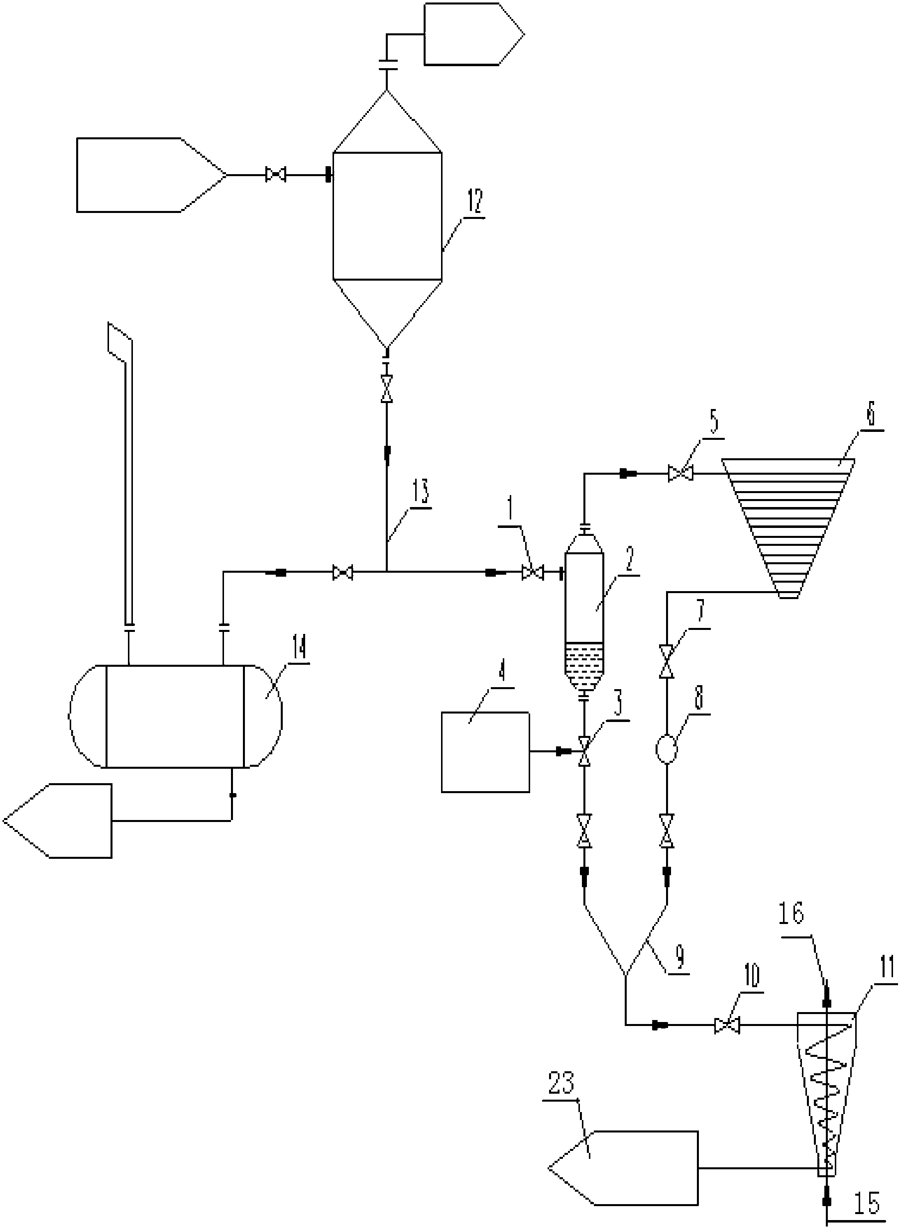
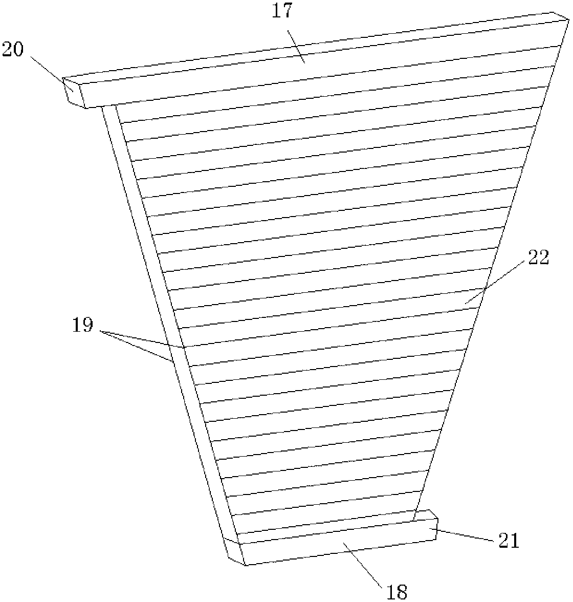
[0022] A steam drum continuous blowdown expansion vessel drainage energy utilization system, such as Figure 1 to Figure 3 As shown, it includes continuous sewage expansion container 12 and regular sewage expansion container 14. Continuous sewage expansion container 12 is connected with regular sewage expansion container 14 through continuous sewage expansion container drainage pipeline 13. 13 is provided with a hydrophobic energy utilization device connected in parallel with the regular sewage expansion vessel 14, and the hydrophobic energy utilization device includes a steam generator 2, a dust collector ash hopper heater 6, a denitrification system liquid ammonia evaporator 11, connecting pipes and valves; The generator 2 is connected to the continuous sewage expansion vessel 12, the steam generator 2 is a vertical structure, the top is a steam outle...


PUM


Abstract

The invention discloses a drain energy utilization system of a steam header continuous blowdown flash tank, which comprises a continuous blowdown flash tank and a periodical blowdown flash tank, wherein the continuous blowdown flash tank is connected with the periodical blowdown flash tank through a continuous blowdown flash tank drain pipeline; a drain energy utilization device connected in parallel with the periodical blowdown flash tank is arranged on the continuous blowdown flash tank drain pipeline, and comprises a steam generator, a dust catcher ash bucket heater, a denitrification system liquid ammonia evaporator, a connecting pipeline and valves, wherein the steam generator is connected with the continuous blowdown flash tank, has a vertical structure and a steam outlet at the top, is connected with a steam inlet on the side surface at the top of the ash bucket heater through the pipeline, and has a drain outlet at the bottom; an adjusting valve is arranged at the drain outlet; a drain outlet is formed on the side surface of the bottom of the dust catcher ash bucket heater; the denitrification system liquid ammonia evaporator is provided with a heating medium inlet, a heating medium outlet, a liquid ammonia pipeline inlet and a gas ammonia pipeline outlet; and the drain outlets of the steam generator and the ash bucket heater are connected with the heating medium inlet of the denitrification system liquid ammonia evaporator through a drain converged pipeline.

Description

technical field [0001] The invention relates to the technical field of steam drum continuous blowdown, in particular to a steam drum continuous blowdown expansion vessel drainage energy utilization system. Background technique [0002] In the prior art, the steam drum is usually discharged from the bottom of the expansion vessel for continuous sewage discharge and expansion vessel, and then enters the regular sewage discharge expansion vessel for expansion and decompression. Part of it is discharged into the atmosphere through the exhaust pipe in the form of steam, and the rest is drained from the bottom drain of the expansion vessel in the form of water. Discharged, and mixed with cooling water to cool down to below 70°C, enter the drainage tank, and then enter the water treatment system for treatment and reuse. This method of hydrophobic treatment of the expander will cause a waste of hydrophobic energy, and the steam discharged into the atmosphere from the exhaust pipe wi...

Claims


Application Information

Patent Timeline
Patent Type & Authority Applications(China)
IPC IPC(8): F22B37/54F22B1/16
Inventor 侯庆伟祁金胜蒋莉李官鹏于洪涛高振宝张军梅王妮妮冯玉滨
Owner SHANDONG ELECTRIC POWER ENG CONSULTING INST CORP
Learn More