Shell-and-tube heat exchanger adopting copper heat exchange tube

A shell-and-tube heat exchanger and heat exchange tube technology, applied in the direction of heat exchanger shell, heat exchange equipment, evaporator/condenser, etc., can solve the problem of large space occupation, low heat exchange efficiency and large heat exchanger volume. and other problems, to achieve the effect of reducing elongation, increasing the bonding rate and improving sealing performance

Inactive Publication Date: 2012-10-03
苏州利玛特能源装备有限公司
View PDF2 Cites 6 Cited by
  • Summary
  • Abstract
  • Description
  • Claims
  • Application Information

AI Technical Summary

Problems solved by technology

However, the strength welding method is not suitable for heat exchangers where the heat exchange tube is copper tube and the tube sheet is carbon tube sheet, because copper and steel have problems such as large difference in melting point, large difference in shrinkage rate, and large difference in thermal conductivity. In this way, when the copper pipe and carbon steel pipe plate pipe head are welded, the weldability of copper and steel is poor, the fusion is difficult during welding, and defects such as thermal stress, slag inclusion and thermal cracks are generated. Under the design pressure of 12 MPa, the pipe head None of the welded joints can meet the strength requirements, resulting in leakage
[0004] It is also known that in the field of coal mines, there are more and more coal mines with mining depths of 1000 meters, and the design pressure requirements for the water side of the heat exchanger are also increasing. The higher it is, the ordinary strength expansion can no longer meet the requirements
Although the steel tube heat exchange tube-shell-and-tube heat exchanger is adopted, and the steel tube heat exchange tube is welded to the tube sheet, which can meet the pressure requirements, but the heat exchange efficiency of the steel tube heat exchange tube is lower than that of the copper tube. For the same heat exchange area, the volume needs to be increased by 30%~40%, which will lead to a larger volume of the heat exchanger of the air conditioning unit and take up a lot of space

Method used


Image

  • Shell-and-tube heat exchanger adopting copper heat exchange tube
  • Shell-and-tube heat exchanger adopting copper heat exchange tube

Examples


Embodiment Construction

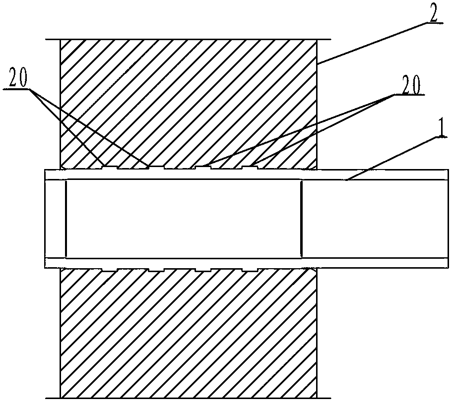
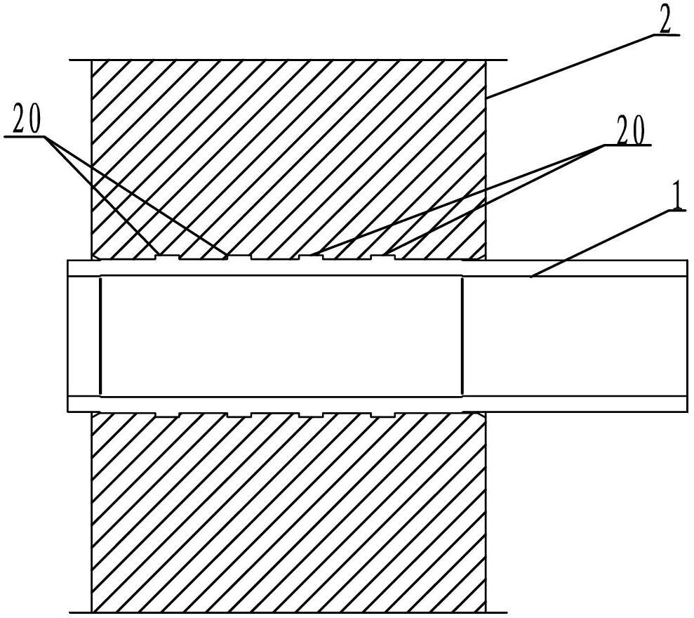
[0016] This embodiment provides a shell-and-tube heat exchanger using copper heat exchange tubes. Such as figure 1 As shown, the shell-and-tube heat exchanger includes a copper heat exchange tube 1 and a carbon tube plate 2, and the copper heat exchange tube 1 and the carbon tube plate 2 are expanded together. On the inner wall of the hole of the carbon tube plate 2 , there are four grooves 20 distributed at intervals along the extending direction of the centerline of the hole of the carbon tube plate 2 . The depth of the groove 20 is 0.5 mm, and the distance between two adjacent grooves is 10 mm. The distance between the outermost groove 20 on the sealing surface and the edge of the carbon tube sheet 2 is 8-10 mm.

[0017] The shell-and-tube heat exchanger provided in this embodiment breaks through the limitations of traditional heat exchangers that the design pressure of expansion tubes is less than or equal to 4.0Mpa, and can ensure strength and sealing under a desig...


PUM


Abstract

The invention discloses a shell-and-tube heat exchanger adopting a copper heat exchange tube, which comprises the copper heat exchange tube and a carbon tube plate. The heat exchanger is characterized in that the copper heat exchange tube is in expanded connection with the carbon tube plate; at least four grooves which are distributed at intervals along the extending direction of the center line of a hole of the carbon tube plate are formed on the inner wall of the hole of the carbon tube plate; the depths of the grooves are 0.4 to 0.6mm; and the distance between each two adjacent grooves is 8 to 12mm. By forming at least four grooves with specific depths on the inner wall of the hole of the carbon tube plate and limiting the distance of each adjacent grooves, the sealing performance is improved during the tube expansion, the conjoint ratio of the heat exchange tube and the tube plate is increased, and the purpose that a tube head of the heat exchanger is not exposed under high pressure can be achieved. In addition, by adopting the structure, the extending length of the heat exchange tube is effectively reduced after the expanded connection, so that the heat exchanger can totally meet the requirements of underground air-conditioning unit heat exchangers in the coal mine field.

Description

technical field [0001] The invention relates to a shell-and-tube heat exchanger, in particular to a shell-and-tube heat exchanger suitable for underground air-conditioning equipment in coal mines. Background technique [0002] The shell-and-tube heat exchanger, also known as the shell-and-tube heat exchanger, is a partitioned heat exchanger that uses the wall of the tube bundle enclosed in the shell as the heat transfer surface. This kind of heat exchanger has a relatively simple structure and reliable operation. It can be made of various structural materials (mainly metal materials), and can be used under high temperature and high pressure. It is the most widely used type at present. [0003] In the prior art, the shell-and-tube heat exchanger with a design pressure of less than 4.0 MPa mainly realizes the connection between the heat exchange tube and the tube sheet through expansion joints. The expansion joints include mechanical expansion joints and uniform expansio...

Claims


Application Information

Patent Timeline
Patent Type & Authority Applications(China)
IPC IPC(8): F25B39/00F28F9/26F28F9/013
Inventor 喻建媛
Owner 苏州利玛特能源装备有限公司
Why Eureka
Try Eureka