
Magnetic antenna for improving penetrability of electromagnetic wave in plasma

A plasma and magnet antenna technology, applied in antennas, loop antennas, antenna grounding devices, etc., can solve the problems of unable to meet the high gain requirements of antennas, small gain of microstrip antennas, high microstrip antennas, etc., to achieve increased frequency bandwidth, circular Effects of Polarized Bandwidth Improvement and Gain Improvement

Inactive Publication Date: 2012-10-03
UNIV OF ELECTRONICS SCI & TECH OF CHINA
View PDF4 Cites 9 Cited by
  • Summary
  • Abstract
  • Description
  • Claims
  • Application Information

AI Technical Summary

Problems solved by technology

This is because the Q value of the microstrip antenna is very high, and the S11 bandwidth is relatively narrow, and the circular polarization can be satisfied at a certain frequency point by using the angle-cutting method, but the circular polarization bandwidth is not too wide, and the gain of the microstrip antenna is generally small , unable to meet the high-gain requirements of the antenna of the penetrating plasma microwave communication system

Method used


Image

  • Magnetic antenna for improving penetrability of electromagnetic wave in plasma
  • Magnetic antenna for improving penetrability of electromagnetic wave in plasma
  • Magnetic antenna for improving penetrability of electromagnetic wave in plasma

Examples


Embodiment Construction

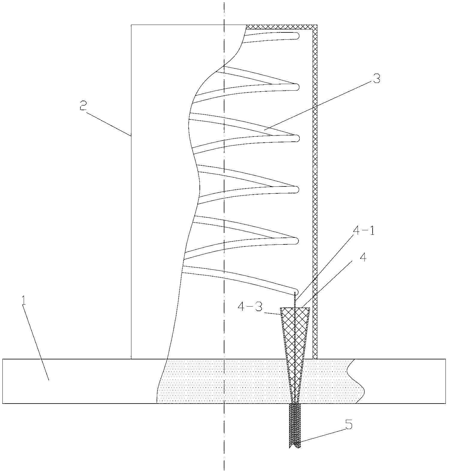
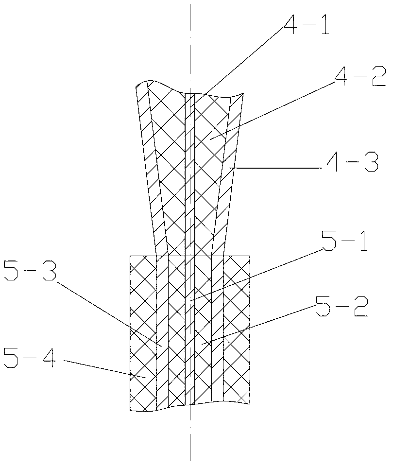
[0010] Take the magnet antenna with a working center frequency of 1.5GHz as an example: the ground plate 1 has a diameter D of 200mm and a thickness of 20mm, and uses N52 rare earth NdFeB permanent magnets with a conductivity of 625000 Siemens / m and a maximum residual magnetic strength of 1.43 Between -1.48, the maximum magnetic energy product is 398-422 kJ / m3; the radome 2 adopts a cylindrical radome with a sealing head at the top, its inner diameter is Φ80mm, its height is 150mm, and its thickness is 2mm. High-temperature-resistant polytetrafluoroethylene material, the radome is covered behind the helical antenna 3 and the cone-shaped coaxial wire post 4, and its lower opening is sealed and fixed with the grounding plate; the material of the helical antenna 3 is copper strips, and the diameter d is 3mm , the spiral diameter D is 64mm, the pitch S is 23mm, the height h between the lower end of the spiral and the ground plate 1 is 30mm, and the impedance is 140.7 ohms; the leng...


PUM


Abstract

The invention belongs to a magnetic antenna for high-speed aircraft navigation and communication, which comprises a columnar spiral antenna, a closed antenna cover, a strong magnet ground plate and a conical coaxial feeding wire column. In the magnetic antenna, the spiral antenna of an axial mode is adopted, the antenna and a strong permanent magnet are integrated, the magnet serves as a magnetic field generator to generate a high permanent field and also serves as the antenna ground plate, when magnetic field intensity B is more than or equal to 0.5T, signal emitted by the spiral antenna can effectively penetrate a plasma, when the magnetic field of the permanent magnet is increased to 1.0T, antenna gain is increased to 9.6dB and approaches 10.6dB of the antenna gain in air, and the attenuation of electromagnetic wave during transmission in the plasma is reduced by 30dB. Therefore, the magnetic antenna has the characteristics of frequency bandwidth, circular polarization bandwidth, low attenuation amplitude of the electromagnetic wave of the antenna and the like, the antenna gain and the penetrability of the plasma are effectively improved, and the defect of communication interrupt caused by the existence of a surface plasma sheath in a background technology is overcome.

Description

technical field [0001] The invention belongs to a magnet antenna for navigation and communication of high-speed aircraft, in particular to a three-dimensional helical antenna for plasma sheaths on the surface of the aircraft. The attenuation of the electromagnetic wave radiated by the antenna in the plasma can be greatly reduced, thereby overcoming the communication interruption problem between the aircraft and the ground caused by the plasma sheath on the surface of the aircraft. Background technique [0002] When the aircraft flies through the atmosphere at hypersonic speed, the high-temperature gas around the aircraft will be partially ionized to form plasma. During the propagation of electromagnetic waves through the plasma sheath, due to reflection, refraction and absorption by the plasma sheath, the energy will be greatly attenuated, and even the transmission will be completely interrupted. At present, the main measures to reduce the attenuation of electromagnetic wav...

Claims


Application Information

Patent Timeline
Patent Type & Authority Applications(China)
IPC IPC(8): H01Q1/22H01Q1/42H01Q1/48H01Q1/50H01Q7/00
Inventor 赵青邢晓俊唐剑明
Owner UNIV OF ELECTRONICS SCI & TECH OF CHINA
Learn More