Gear milling spindle box directly driven by torque motor

A technology of torque motor and spindle box, which is used in driving devices, metal processing machinery parts, manufacturing tools, etc., can solve the problems of vibration lines on the machined surface, easy pitting of gears, and poor rigidity, so as to avoid impact pitting and transmission. Short path, improved surface roughness effect

Active Publication Date: 2014-09-10
NANJING GONGDA CNC TECH
View PDF5 Cites 0 Cited by
  • Summary
  • Abstract
  • Description
  • Claims
  • Application Information

AI Technical Summary

Problems solved by technology

[0006] Aiming at technical problems such as poor rigidity of the overall structure, high noise, easy pitting of the gears, and vibration marks on the machined surface of the gear-driven spindle box, the present invention proposes a torque motor direct-drive gear milling spindle based on a torque motor and a synchronous belt drive. box

Method used


Image

  • Gear milling spindle box directly driven by torque motor
  • Gear milling spindle box directly driven by torque motor

Examples


Embodiment Construction

[0028] specific implementation plan

[0029] In order to further understand the content, characteristics and functions of the present invention, through the following implementation examples, and in conjunction with the accompanying drawings, the description is as follows:

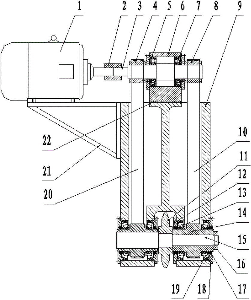
[0030] A torque motor direct-drive milling gear spindle box, comprising a low-speed high-torque torque motor 1, an active synchronous pulley shaft 3, a first active synchronous pulley 4, a second active synchronous pulley 8, a main shaft case 9, a motor bracket 21, The first synchronous belt 10, the second synchronous belt 20, the disc milling cutter 11, the passive synchronous pulley shaft 14 and the tool bar 15, the low-speed high-torque torque motor 1 is connected with the active synchronous pulley shaft 3, and the active synchronous pulley shaft 3 The two ends are respectively provided with a first active synchronous pulley 4 and a second active synchronous pulley 8, the first active synchronous pulley...


PUM


Abstract

A gear milling spindle box directly driven by a torque motor is characterized by comprising the low-speed high-torsion torque motor (1), a driving synchronous belt pulley axle (3), a first driving synchronous belt pulley (4), a second driving synchronous belt pulley (8), a spindle box body (9), a motor support (21), a first synchronous belt (10), a second synchronous belt (20), a disc milling cutter (11), a driven synchronous belt pulley axle (14) and a cutter bar (15). The low-speed high-torsion torque motor is directly connected with the disc milling cutter by the tensioned synchronous belts with arc teeth, a transmission path is short, and transmission efficiency is high. In addition, the tensioned synchronous belts can realize stable transmission without backlashes, nonlinear vibration of a transmission system due to fluctuating cutting load is avoided, cutting noise is lowered, surface roughness of a cut tooth surface is improved, and the risks of impact pitting corrosion of the tooth surface during gear transmission are avoided.

Description

technical field [0001] The invention relates to gear machining equipment, in particular to a torque motor direct-driven milling spindle box of a cylindrical gear numerical control milling machine. Background technique [0002] Large cylindrical gears are widely used in mechanical transmission in mining, metallurgy, chemical industry and other industries, and are very important basic parts of mechanical manufacturing. The traditional method of machining large cylindrical gears usually adopts hobbing or slotting, which is very inefficient. In recent years, with the technological development of numerical control technology, cutting tool technology and other related fields, the process of milling large gears with numerical control forming gear milling machines has been gradually popularized and applied. The CNC forming gear milling machine is equipped with a forming disc milling cutter with non-regrinding blades, and uses the non-instant center envelope method to directly mill ...

Claims


Application Information

Patent Timeline
Patent Type & Authority Patents(China)
IPC IPC(8): B23B19/00B23F5/20B23Q5/10
Inventor 方成刚黄筱调洪荣晶于春建
Owner NANJING GONGDA CNC TECH
Why Eureka
Try Eureka