Supercharge Your Innovation With Domain-Expert AI Agents!

Dedicated clamp for abrasive buff stick

A special fixture and grinding rod technology, applied in the direction of the work carrier, can solve the problems of low processing production efficiency, scrapped internal materials, low work efficiency, etc., and achieve the effects of high work efficiency, easy clamping, and simple structure

Inactive Publication Date: 2012-10-10
ZHENGZHOU DIAMOND PRECISION MFG
View PDF10 Cites 2 Cited by
  • Summary
  • Abstract
  • Description
  • Claims
  • Application Information

AI Technical Summary

Problems solved by technology

[0003] When processing and grinding grinding tools, the whole set of matching grinding tools must be in the production and processing workshop, so as to ensure that the processed grinding bars meet the supporting requirements, the operation is extremely inconvenient, time-consuming and laborious, and the work efficiency is low
In addition, the existing grinding bar is formed by machining the outer diameter of the bar first, and then cutting the inside. The internal material is scrapped, raw materials are wasted, the processing cost is high, and the processing production efficiency is low.

Method used


Image

  • Dedicated clamp for abrasive buff stick
  • Dedicated clamp for abrasive buff stick
  • Dedicated clamp for abrasive buff stick

Examples


Embodiment 1

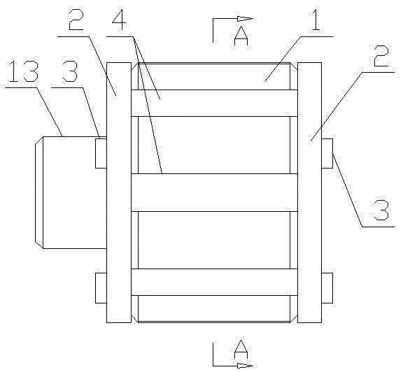
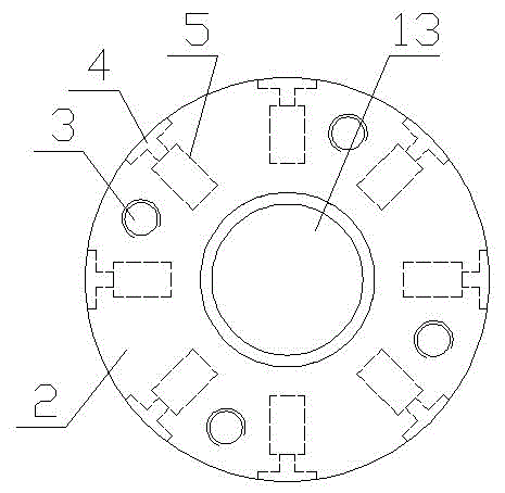
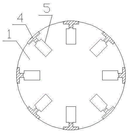
[0025] Example 1, such as Figure 1-7 The special fixture for grinding bars shown includes a fixture body 1, one end of the fixture body 1 is provided with a cylindrical step 13, and eight connected grinding bar installation grooves 11 and magnet installation grooves are evenly distributed on the circumferential surface of the fixture body 1. 12. The bottom of the grinding rod installation groove 11 is in communication with the top of the magnet installation groove 12, the grinding rod installation groove 11 is T-shaped, and the magnet installation groove 12 is square. A magnet 5 is arranged in the magnet mounting groove 12, a grinding rod 4 is installed in the grinding rod installation groove 11, and the bottom of the grinding rod 4 is adsorbed together with the magnet 5, and the magnet 5 plays a radial positioning effect on the grinding rod 4, and the grinding rod 4 is connected to the magnet 5. The shape of the grinding bar installation groove 11 is adapted, and the outer s...

Embodiment 2

[0028] Example 2, such as Figure 8-10 The special clamp for grinding bars shown is different from Embodiment 1 in that: the circumferential surface of the clamp body 6 is evenly provided with twelve connected grinding rod installation grooves 61 and magnet installation grooves 62, and the clamp body 6 A cylindrical step 63 is provided at one end.

[0029] Not limited to the above-mentioned embodiments, the maximum outer diameter of the fixture body and the number of the grinding bar installation slots and magnet installation slots in the present invention depend on the arc outer diameter of the grinding bar 4 and the width of the grinding bar 4, and can also be processed according to customer needs Fixture body with 4 or 16 grinding rod installation slots and magnet installation slots.


PUM


Abstract

The invention discloses a dedicated clamp for an abrasive buff stick, which comprises a clamp body, wherein an abrasive buff stick mounting groove is formed in the circumference surface of the clamp body; a magnet mounting groove is formed in the lower surface of the abrasive buff stick mounting groove and is communicated with the abrasive buff stick mounting groove; a magnet is arranged in the magnet mounting groove; and locking discs are fixedly arranged at two ends of the clamp body. The dedicated clamp for the abrasive buff stick achieves a simple structure, the magnet plays a role in positioning the abrasive buff stick in the radial direction, the locking discs play a role in positioning the abrasive buff stick in the axial direction, the abrasive buff stick is clamped by utilizing a magnet positioning and locking disc positioning combined fixation method, and the dedicated clamp is simple and convenient to clamp.

Description

technical field [0001] The invention belongs to the technical field of clamps for grinding tools, in particular to a special clamp for grinding bars. Background technique [0002] At present, the grinding part of the grinding tool is mainly a grinding rod, which is made of a bearing steel substrate and a diamond coating, and the diamond coating participates in grinding. Grinding is a method of hole finishing, which needs to be carried out on the basis of fine boring, fine reaming or fine grinding. Its working principle is: under a certain pressure, the grinding rod contacts the surface of the workpiece and produces complex relative motion. That is, rotary motion, reciprocating motion, or radial motion of pressure. During the motion, the diamond coating on the grinding rod plays the role of cutting, scraping and extrusion, and cuts extremely thin chips from the surface of the workpiece (the chips are mainly produced in the previous process. bumps left on the workpiece surfac...

Claims


Application Information

Patent Timeline
IPC IPC(8): B24B37/27
Inventor 边卫锋张凤鸣徐华鸣齐磊张嗣静张伟峰杨永磊
Owner ZHENGZHOU DIAMOND PRECISION MFG
Features
  • R&D
  • Intellectual Property
  • Life Sciences
  • Materials
  • Tech Scout
  • Unparalleled Data Quality
  • Higher Quality Content
  • 60% Fewer Hallucinations
Learn More