Hot blast heater realizing preheated combustion of horizontal spraying heat accumulator of premixed air flow of gas and air

A technology of air premixing and horizontal injection, applied in the direction of brick blast furnaces, etc., can solve the problems of uneven mixing, uneven air distribution, complex burner structure, etc.

Inactive Publication Date: 2012-10-10
郑州豫兴热风炉科技有限公司
View PDF4 Cites 6 Cited by
  • Summary
  • Abstract
  • Description
  • Claims
  • Application Information

AI Technical Summary

Problems solved by technology

[0003] In view of the above situation, in order to overcome the defects of the prior art, the object of the present invention is to provide a hot blast stove in which gas and air premixed air flow is horizontally injected into the regenerator for preheating and burning, which can effectively solve the problem that the original sleeve burner cooperates with the combustion chamber to complete the gas Many problems that are prone to occur during mixed combustion with air combustion chambers, such as low mixing rate of gas and air, uneven mixing, and the resulting low combustion intensity, incomplete combustion, uneven air flow distribution, and the need for larger combustion chambers Issues such as space and complex burner structures

Method used


Image

  • Hot blast heater realizing preheated combustion of horizontal spraying heat accumulator of premixed air flow of gas and air
  • Hot blast heater realizing preheated combustion of horizontal spraying heat accumulator of premixed air flow of gas and air
  • Hot blast heater realizing preheated combustion of horizontal spraying heat accumulator of premixed air flow of gas and air

Examples


Embodiment Construction

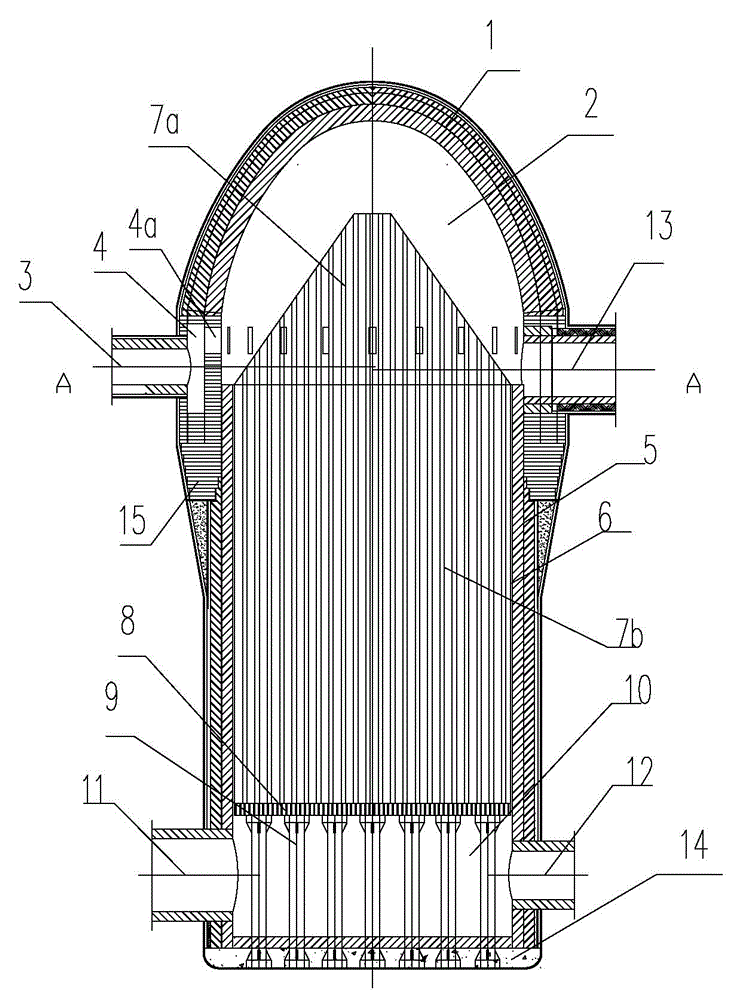
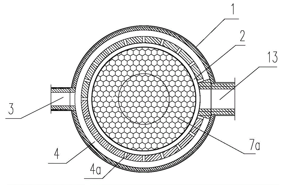
[0011] The specific implementation manners of the present invention will be described in detail below in conjunction with the accompanying drawings.

[0012] Depend on Figure 1-Figure 5 Given, the present invention includes a combustion chamber wall 1, a combustion chamber 2, a regenerator, a mixed air intake pipe 3, a mixed air distribution ring 4, a mixed air horizontal nozzle 4a, a hot blast stove wall 5, a regenerator 6, Furnace grate 8 and its support column 9, cold air chamber 10, flue gas outlet pipe 11, cold air inlet pipe 12, hot air outlet pipe 13, furnace bottom 14, and labyrinth connection structure 15 between the combustion chamber and the regenerator wall. The chamber wall 1 is composed of a spherical or ellipsoidal vault above and a cylinder below. The space in the combustion chamber wall is the combustion chamber 2. Hot air is arranged on the cylinder of the combustion chamber wall perpendicular to its axis. Outlet pipe 13 and mixed air inlet pipe 3, there is...


PUM


Abstract

The invention relates to a hot blast heater realizing preheated combustion of a horizontal spraying heat accumulator of premixed air flow of gas and air, effectively solving the problems that the mixing is slow and nonuniform, the combustion strength is insufficient and incomplete, larger combustion chamber is required, and a combustor is complex. The hot blast heater has the structure as follows: a hot air outlet pipe and a mixed air flow inlet pipe are arranged on the wall of a combustion chamber; a distribution annular channel communicated with the mixed air flow inlet pipe is arranged in the inner wall of the wall of the combustion chamber; a spray nozzle communicated with the combustion chamber in the wall of the combustion chamber is arranged at the inner side of the distribution annular channel; a grate positioned in a cold air chamber is arranged on the lower part of a heat accumulation chamber on the lower part of the combustion chamber; a heat accumulator is arranged in the heat accumulation chamber; a support pillar fixed at a blast bottom is arranged on the lower part of the grate; the grate, the wall of the hot blast heater and the grate bottom form the cold air chamber; an exhaust gas outlet pipe and a cold air inlet pipe are arranged on the cold air chamber; and a labyrinth connection structure is formed between the upper part of the wall of the hot blast heater and the lower part of the wall of the combustion chamber. According to the invention, a simple sleeve combustor is adopted, and high-strength combustion is realized by virtue of the heat accumulator, the structure of the hot blast heater is simplified and is compact so that the investment cost is reduced, and the hot blast heater is stable in structure.

Description

technical field [0001] The invention relates to a hot blast stove for preheating and burning a regenerator with a gas and air premixed airflow horizontally spraying a regenerator for providing high-temperature blast for a blast furnace. Background technique [0002] Among the currently used hot blast stoves, there is a type of top-fired hot blast stove with a sleeve burner. Because of the structure and arrangement of the sleeve burner, it can neither complete the good mixing of gas and air flow, but also make the gas entering The airflow in the combustion chamber rotates upwards and then turns downwards, and enters the regenerator in an uneven distribution. Therefore, such a flow combustion mode always has problems such as uneven mixing, incomplete combustion, improper use of combustion chamber space, and uneven airflow distribution. If the airflow arrangement in the combustion chamber and regenerator of the hot blast stove is not properly arranged (flow rate selection, air...

Claims


Application Information

Patent Timeline
Patent Type & Authority Applications(China)
IPC IPC(8): C21B9/02
Inventor 陈云鹤
Owner 郑州豫兴热风炉科技有限公司
Why Eureka
Try Eureka