
Fuel supply system of diesel engine

A diesel engine and fuel supply technology, which is applied in the direction of engine components, machines/engines, and charging systems, can solve the problems of reduced engine working efficiency, increased engine fuel pressure loss, and poor fuel atomization effects, etc., to achieve improved The effect of power performance and economic performance, balanced fuel pressure loss, and good atomization effect

Active Publication Date: 2012-10-10
GREAT WALL MOTOR CO LTD
View PDF6 Cites 11 Cited by
  • Summary
  • Abstract
  • Description
  • Claims
  • Application Information

AI Technical Summary

Problems solved by technology

Fuel is an important medium in the fuel supply system of the engine, and changes in its temperature will lead to changes in the degree of atomization in the combustion chamber and the flow rate of the injector, which will affect the working efficiency of the engine
[0003] The fuel supply method of traditional diesel engines is: fuel tank - fuel pump - fuel filter - high pressure oil pump - fuel rail - fuel injector - diesel engine combustion chamber, since there is no temperature control device in the fuel supply system, the external Conditions and internal factors greatly affect fuel temperature
When the external ambient temperature is low, the fuel temperature decreases accordingly, not only the fuel viscosity increases, the flow resistance increases, but also the atomization effect of the fuel is not good, the thermal efficiency of the engine decreases, which is not conducive to the start of the engine and the rapid warm-up of the car; when the external environment When the temperature is high, the fuel temperature rises accordingly, the flow loss of the fuel increases, bubbles will be generated in the fuel pipeline, and cavitation will occur, which will negatively affect the normal supply of fuel to the engine
In addition, the fuel pipeline of the traditional diesel engine fuel supply system is long, which increases the pressure loss of the engine fuel oil and reduces the working efficiency of the engine.

Method used


Image

  • Fuel supply system of diesel engine
  • Fuel supply system of diesel engine
  • Fuel supply system of diesel engine

Examples


Embodiment Construction

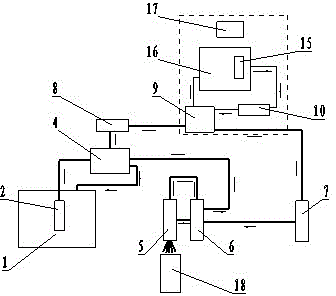
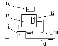
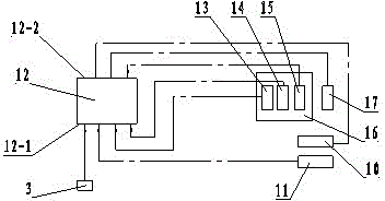
[0018] See Figure 1, figure 2 , the present invention is provided with a fuel temperature regulating device and an auxiliary fuel pump 8, and the fuel temperature regulating device includes a fuel temperature regulating actuator and an electronic control unit. The auxiliary fuel pump 8 is located behind the fuel filter 4 in the fuel supply system. The fuel temperature adjustment actuator is located between the auxiliary fuel pump 8 and the high-pressure oil pump 7 in the fuel supply system, and it includes a heat exchanger 9, a water tank 16, a cooling fan 17 and an electronic water pump 10, and the heat exchanger 9 circulates water To adjust the temperature of the fuel oil for the heat exchange medium, a fuel oil circulation channel and a circulating water circulation channel are provided inside the heat exchanger 9, and the circulation directions of the fuel oil and the circulating water inside the heat exchanger 9 are opposite; the inside of the water tank 16 is provided w...


PUM


Abstract

The invention discloses a fuel supply system of a diesel engine, which is used for improving the power performance and economic performance of the diesel engine. The system is provided with a fuel temperature adjusting device and an auxiliary fuel pump, wherein the auxiliary fuel pump is located behind a fuel filter in the fuel supply system; the fuel temperature adjusting device comprises a fuel temperature adjusting execution mechanism and an electronic control unit; and the fuel temperature adjusting execution mechanism is located between the auxiliary fuel pump and a high-pressure oil pump in the fuel supply system. In the invention, the fuel temperature adjusting device arranged in the fuel supply system is not influenced by external conditions and internal factors and can keep constant best temperature of fuel supply, thereby improving the power performance and economic performance of the engine.

Description

technical field [0001] The invention relates to a diesel engine fuel supply system capable of controlling the fuel temperature, belonging to the technical field of engines. Background technique [0002] With the rapid development of the world's automobile industry, energy-saving, environmental protection, and high-performance engines have become the focus of the times. The application of new technologies and the formation of control theories have deepened people's understanding of engines and promoted the continuous improvement of engine technology. . At present, more scholars and experts are paying more and more attention to the influence of changes in some physical parameters on engine performance, such as engine fuel temperature, engine oil temperature, intake pressure, exhaust temperature, cooling medium temperature, etc. Fuel oil is an important medium in the fuel supply system of the engine, and changes in its temperature will lead to changes in the degree of atomizat...

Claims


Application Information

Patent Timeline
IPC IPC(8): F02M37/18F02M31/125
Inventor 贾殿臣刘大鹏关松
Owner GREAT WALL MOTOR CO LTD
Learn More