Thin-film magnetoresistive sensor element and thin-film magnetoresistive bridge

A magnetoresistive sensor and thin-film technology, applied in the field of half-bridge and full-bridge bridges, can solve the problems affecting sensor performance, limiting chip design, limited bias magnetic field, etc., achieving small hysteresis, low cost, high precision and high linearity

Inactive Publication Date: 2012-10-10
MULTIDIMENSION TECH CO LTD
View PDF8 Cites 13 Cited by
  • Summary
  • Abstract
  • Description
  • Claims
  • Application Information

AI Technical Summary

Problems solved by technology

[0005] The characteristics of the first method are: the process is simple, but the bias magnetic field provided by the shape anisotropy is limited, and it limits the design of the chip
The characteristic of adopting the second method is: the size of the bias magnetic field can be changed by adjusting the composition and thickness of the permanent magnetic film, but in practical applications, it is necessary to avoid the interference of a large external magnetic field. If there is interference of a large magnetic field, the bias will be changed. The direction of the magnetic field, which affects the perf

Method used


Image

  • Thin-film magnetoresistive sensor element and thin-film magnetoresistive bridge
  • Thin-film magnetoresistive sensor element and thin-film magnetoresistive bridge
  • Thin-film magnetoresistive sensor element and thin-film magnetoresistive bridge

Examples


Embodiment 1

[0031] Embodiment 1 Thin film magnetoresistive sensor element

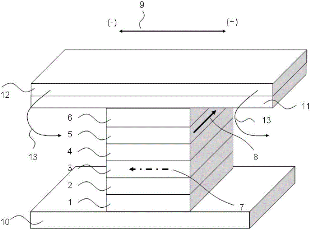
[0032] Such as figure 1 As shown, the structure of the thin film magnetoresistive sensor element is composed of nanoscale multilayer films: lower electrode 10, seed layer 1, antiferromagnetic pinning layer 2, magnetic pinned layer 3 structure, nonmagnetic isolation layer 4, magnetic Free layer 5 , protective layer 6 , upper electrode 11 , and bias layer 12 . The magnetic moment direction of the magnetic pinned layer 3 is shown in 7, the magnetic moment direction 8 of the magnetic free layer 5 is biased by the constant external magnetic field 13 produced by the bias layer 12, and the magnetic moment direction 8 of the magnetic free layer 5 is in line with The magnetic moment directions 7 of the magnetic pinned layers 3 are perpendicular to each other. The magnetic moment direction 8 of the magnetic free layer 5 changes with the magnitude and direction of the applied magnetic field 9 .

[0033] The working princi...

Embodiment 2

[0034] Embodiment 2 Thin film magnetoresistive bridge half bridge

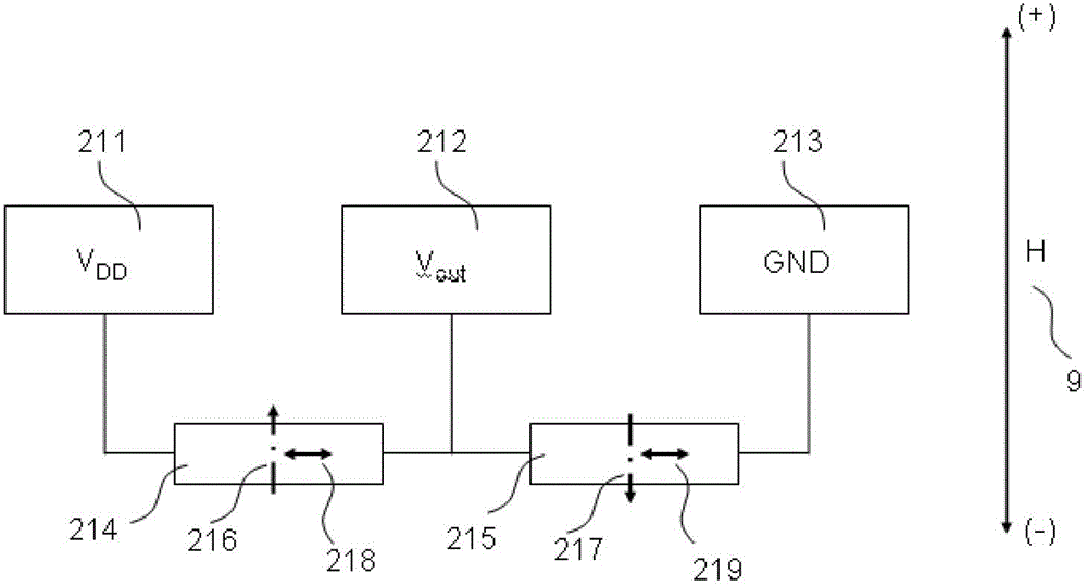
[0035] The structure of the thin film magnetoresistive bridge half bridge, such as image 3As shown, two thin film magnetoresistive elements 214 and 215 are formed. The magnetic moment direction 216 of the magnetic pinned layer of the thin film magnetoresistive element 214 is antiparallel to the magnetic moment direction 217 of the magnetic pinned layer of the thin film magnetoresistive element 215 . The directions 218 and 219 of the magnetic free layers of the thin film magnetoresistive elements 214 and 215 are parallel to each other. The electrodes 211 and 213 are the voltage input terminals of the half-bridge of the thin-film magnetoresistive bridge, and the electrode 212 is the voltage output terminal of the half-bridge of the thin-film magnetoresistive bridge.

[0036] The working principle of the thin film magnetoresistive bridge half bridge, such as Figure 4 As shown, the output voltage V of the hal...

Embodiment 3

[0037] Embodiment 3 Thin film magnetoresistive bridge full bridge

[0038] The structure of the thin film magnetoresistive bridge full bridge, such as Figure 5 As shown, it consists of four thin film magnetoresistive elements 311, 312, 313, 314. The magnetic moment directions 321 , 323 of the magnetic pinned layers of the thin film magnetoresistive elements 311 and 314 are antiparallel to the magnetic moment directions 322 , 324 of the magnetic pinned layers of the thin film magnetoresistive elements 312 , 313 . The directions 331 , 332 , 333 , 334 of the magnetic free layers of the thin film magnetoresistive elements 311 , 312 , 313 , 314 are parallel to each other. The electrodes 315 and 316 are the voltage input ends of the full bridge of the thin film magnetoresistive bridge, and the electrodes 317 and 318 are the voltage output ends of the full bridge of the thin film magnetoresistive bridge.

[0039] The working principle of the thin film magnetoresistive bridge full ...


PUM


Abstract

The invention relates to a thin-film magnetoresistive sensor element. The thin-film magnetoresistive sensor element comprises a lower electrode, a seed layer, an anti-ferromagnetic pinning layer, magnetic nail-pinning layer structure, a non-magnetic isolation layer, a magnetic free layer, a protecting layer, an upper electrode and a magnetic biasing layer. The invention also relates to a bridge for the thin-film magnetoresistive sensor. The thin-film magnetoresistive sensor element and the bridge thereof disclosed by the invention have the characteristics of small magnetic retardation, high precision and linearity, adjustable linear range, simple process, high response frequency, low cost, strong anti-jamming property and favorable temperature characteristic.

Description

technical field [0001] The invention relates to a thin-film magnetoresistance sensor and a half-bridge and a full-bridge composed of the thin-film magnetoresistance. Background technique [0002] Thin film magnetoresistive sensor elements are widely used in data storage (computer hard disk, MRAM), current measurement, position measurement, object movement and speed, angle and angular velocity measurement. [0003] The thin film magnetoresistive sensor element has a multilayer film structure and a spin valve structure. A multilayer film structure includes magnetic and nonmagnetic layers, which are alternately deposited on a substrate. The spin valve structure includes nonmagnetic pinning layer (MnIr, MnPt), magnetic pinned layer (CoFeB, CoFe, or SAF structure CoFe / Ru / CoFe, etc.), nonmagnetic isolation layer (Cu, AlO, MgO, HfO , ZrO, TaO, etc.), magnetic free layer (CoFeB, CoFe, or SAF structure CoFe / Ru / CoFe, etc.). [0004] When the thin film magnetoresistive sensor elemen...

Claims


Application Information

Patent Timeline
IPC IPC(8): G01D5/12G01R33/09G01R17/00
Inventor 王建国
Owner MULTIDIMENSION TECH CO LTD
Why Eureka
Try Eureka