Optical network switching nodes, optical burst synchronization method and circuit frame of multi-frame cluster

A line frame, optical burst technology, applied in the field of network communication, can solve the problem of power consumption limitation multi-frame cluster implementation, etc., to achieve the effect of improving bandwidth utilization, low power consumption, and increasing capacity

Active Publication Date: 2012-10-10
HUAWEI TECH CO LTD
View PDF3 Cites 30 Cited by
  • Summary
  • Abstract
  • Description
  • Claims
  • Application Information

AI Technical Summary

Problems solved by technology

[0005] The present invention provides an optical network switching node of a multi-frame cluster, an optical burst synchronization method, and a line frame to solve the problem of optical burst synchronization, to realize a multi-frame cluster system based on OTN technology, to increase system capacity, and to meet increasingly Increased bandwidth requirements, and then solve the problem that the existing technology of electric switching nodes is limited by the large power consumption of multi-frame clusters

Method used


Image

  • Optical network switching nodes, optical burst synchronization method and circuit frame of multi-frame cluster
  • Optical network switching nodes, optical burst synchronization method and circuit frame of multi-frame cluster
  • Optical network switching nodes, optical burst synchronization method and circuit frame of multi-frame cluster

Examples


Embodiment Construction

[0042] In order to make the purpose, technical solutions and advantages of the embodiments of the present invention clearer, the technical solutions in the embodiments of the present invention will be clearly and completely described below in conjunction with the drawings in the embodiments of the present invention. Obviously, the described embodiments It is a part of embodiments of the present invention, but not all embodiments. Based on the embodiments of the present invention, all other embodiments obtained by persons of ordinary skill in the art without creative efforts fall within the protection scope of the present invention.

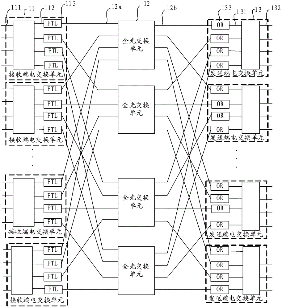
[0043] figure 1 A schematic structural diagram of an optical network switching node of a multi-frame cluster provided by an embodiment of the present invention. Such as figure 1 As shown, the optical network switching node in this embodiment includes: at least one receiving-end electrical switching unit 11 , at least one all-optical switching un...


PUM


Abstract

Embodiments of the present invention provide optical network switching nodes, an optical burst synchronization method and circuit frames of a multi-frame cluster. The synchronization method comprises that: a reference frame is selected, wherein output ports in which the FTLs (fast tunable lasers) in the reference frame are positioned transmit optical burst test signals to receiving ports in which the ORs (optical receivers) in other circuit frames are positioned, and the optical burst test signals carry transmission time slot numbers; and the receiving ports in which the ORs in other circuit frames are positioned, according to optical path difference between the receiving ports to the output ports which the FTLs in the reference frame are positioned, the timing that the receiving ports receive the optical burst test signals and the transmission time slot numbers, obtain the time phase difference between the receiving ports and the reference frame, and then local clock phase calibration is conducted on the basis of time difference phase. With the technical schemes, the problem of optical burst synchronization is solved, an OTN-based multi-frame cluster system is realized, system capacity is increased and power consumption is reduced.

Description

technical field [0001] The embodiment of the present invention relates to network communication technology, and in particular to a multi-frame cluster optical network switching node, an optical burst synchronization method and a line frame. Background technique [0002] With the passage of time, the third generation (3rd-Generation; referred to as: 3G) mobile communication technology, interactive network television (Internet Protocol Television; referred to as: IPTV), video conferencing, streaming media, point-to-point (Point-to- The rapid development of Internet Protocol (Internet Protocol; IP for short) services such as Point (abbreviation: P2P) has resulted in a sharp increase in IP network traffic, and an explosive increase in Internet bandwidth demand. In recent years, Internet traffic has doubled every 12 months, and the capacity of routers has only doubled every 18 months. Internet traffic is growing far faster than the capacity of routers and other devices. The cap...

Claims


Application Information

Patent Timeline
Patent Type & Authority Applications(China)
IPC IPC(8): H04Q11/00H04L12/56
CPCH04Q11/0062H04Q11/00H04B10/0775H04Q11/0066H04Q2011/0045H04Q2011/0033H04Q11/0005H04Q2011/0083H04Q2011/0024H04B10/0773H04Q2011/0088H04Q2011/0035H04Q2011/0018H04Q2011/0032H04Q2011/0056H04L49/1515H04B10/073H04B10/077H04L7/0075H04L7/10H04L2012/5674
Inventor 钟其文
Owner HUAWEI TECH CO LTD
Why Eureka
Try Eureka