
Production method of fiber arrays

A production method and optical fiber array technology, which can be applied in the coating and other directions, can solve the problems of high processing technology requirements, low product qualification rate and high manufacturing cost, and achieve the effects of long processing cycle, simple process and high manufacturing cost.

Inactive Publication Date: 2012-10-17
CHANGZHOU XINSHENG ELECTRONICS
View PDF3 Cites 4 Cited by
  • Summary
  • Abstract
  • Description
  • Claims
  • Application Information

AI Technical Summary

Problems solved by technology

[0006] It can be seen from the production method of the above-mentioned optical fiber array that this method has defects such as extremely difficult processing, high processing technology requirements, cumbersome procedures, long processing cycle, low product qualification rate, and high manufacturing cost.
In addition, the processing of the V-groove must be completed with imported high-end scribing machines, resulting in higher production costs

Method used


Image

  • Production method of fiber arrays
  • Production method of fiber arrays
  • Production method of fiber arrays

Examples


Embodiment Construction

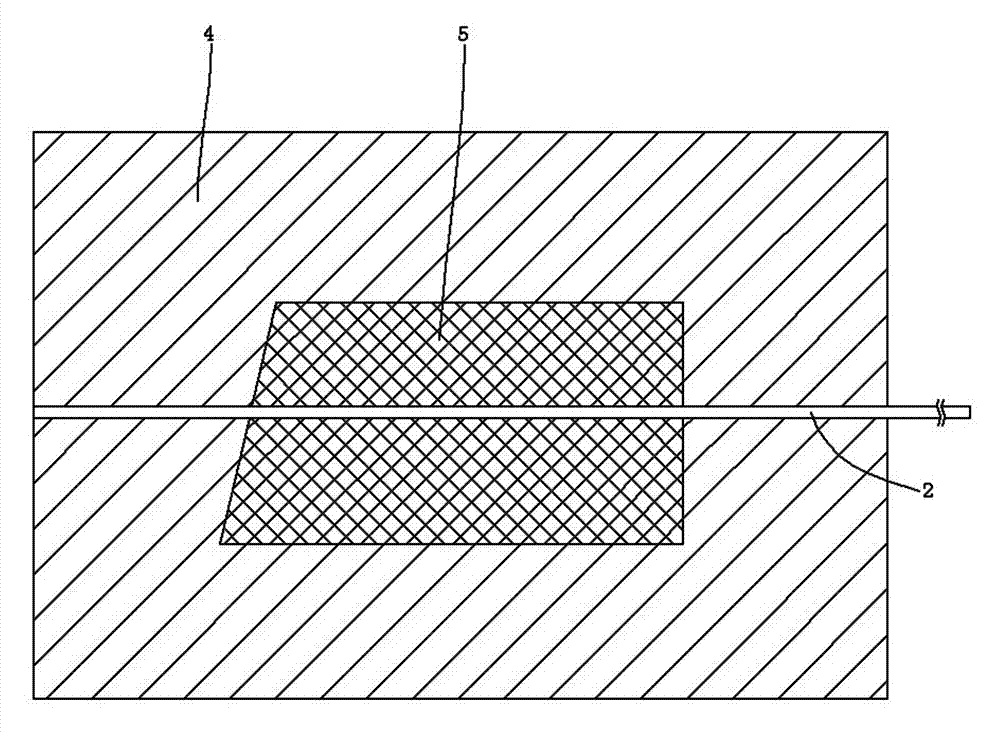
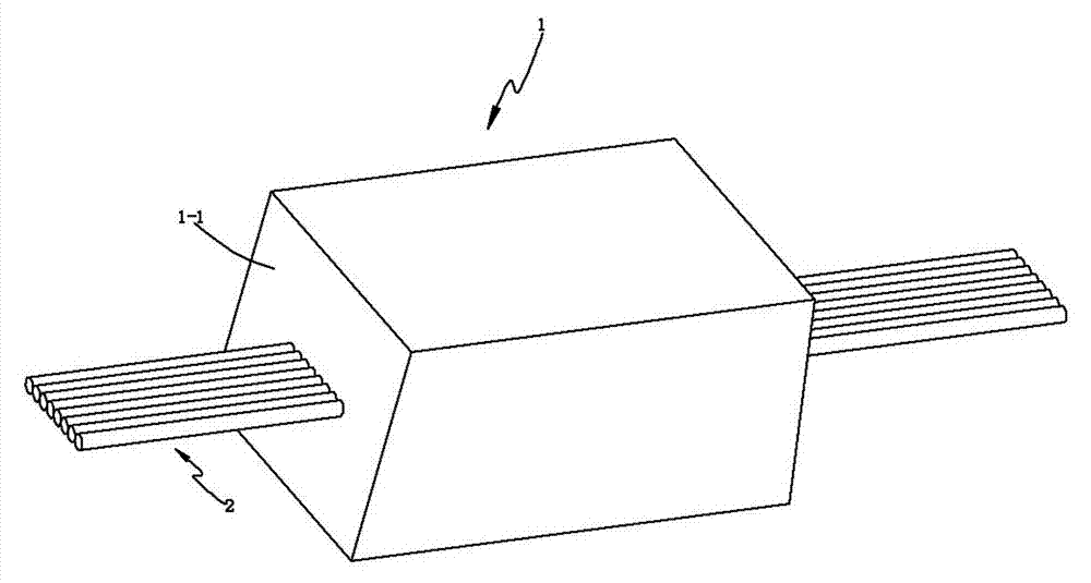
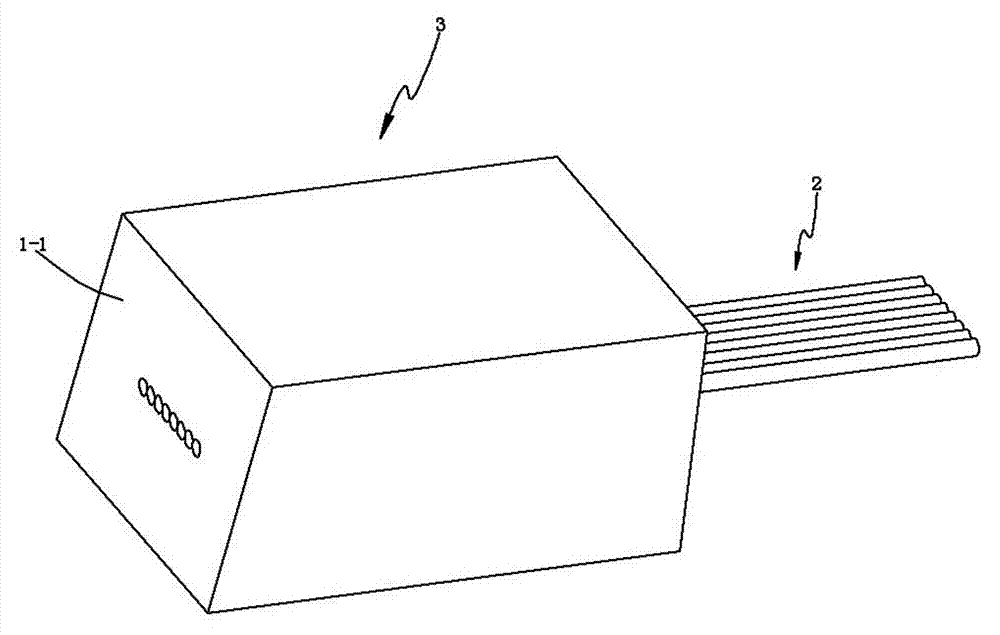
[0022] see Figure 1 to Figure 3 A production method of an optical fiber array shown, the production method comprises the following steps:

[0023] a. Using a common injection molding machine and a conventional injection molding process, using high molecular plastic as the injection molding material, placing the commercially available finished optical fiber ribbon 2 inside the high molecular plastic material 5 in the cavity 4 of the injection molding machine, and injecting one piece at a time Preform 1; in the present invention, such as figure 2 As shown, the preform 1 is preferably in the shape of a right-angled trapezoid, and its end face 1-1 on one side is an inclined plane, and the end face 1-1 is inclined by 8° relative to the vertical plane. With such an inclined end face, the After the array is coupled with the planar optical waveguide chip in the planar optical waveguide splitter, the index of return loss is effectively improved;

[0024] b. Cut off the excess optic...


PUM

PropertyMeasurementUnit
depthaaaaaaaaaa

Abstract

The invention discloses a production method of fiber arrays, which comprises the following steps: adopting an usual injection molding machine and a conventional injection molding technology, adopting high polymer plastic as injection molding materials, placing finished fiber belts available in the market into the high polymer plastic materials in an injection molding machine mold cavity so as to obtain a pre-molded piece through injection molding; cutting off redundant fiber belts from the end face of one side of the pre-molded piece through a sapphire scalpel; adopting a fiber grinding machine to grind the end face of the side of the pre-molded piece after cutting the redundant fiber belts, thus obtain a fiber array. The production method of fiber arrays is simple in technology, short in processing period of the fiber arrays, low in manufacture cost and high in product percent of pass, and greatly reduces processing difficulty of the fiber arrays. The production method is suitable for being popularized and applied to the fiber manufacture field.

Description

technical field [0001] The invention belongs to the technical field of optical fiber manufacturing, in particular to a method for producing an optical fiber array in a planar optical waveguide splitter. Background technique [0002] At present, fiber-to-the-home FTTH has developed rapidly in China, and communication operators put the construction of optical fiber access network in the first place to solve the comprehensive access of voice, video and data in the last mile. The planar optical waveguide splitter is the core optical device for constructing FTTH, which plays the function of optical power distribution, and the optical fiber array is the key component of the planar optical waveguide splitter. [0003] The production method of traditional optical fiber array includes the following two steps: [0004] The first step is to process the V-shaped groove base on the pre-ground quartz glass or silicon substrate with a professional scribing machine. The V-shaped groove bas...

Claims


Application Information

Patent Timeline
Patent Type & Authority Applications(China)
IPC IPC(8): B29C45/00B29K81/00
Inventor 朱钰王艾宁
Owner CHANGZHOU XINSHENG ELECTRONICS
Learn More