Cam shaft with encoding disk and lubricating oil channel

A technology for lubricating oil passages and camshafts, which is applied to engine components, machines/engines, mechanical equipment, etc., can solve the problems of many transmission parts, large mass, and increase in the peripheral size of the engine, and achieves reduced peripheral size and convenient assembly and layout. , the effect of simple structure

Inactive Publication Date: 2012-10-17
东风朝阳朝柴动力有限公司
View PDF5 Cites 4 Cited by
  • Summary
  • Abstract
  • Description
  • Claims
  • Application Information

AI Technical Summary

Problems solved by technology

Problems such as many transmission parts, large mass, and insufficient rigidity of the valve mechanism cause deformation, which may easily lead to the deviation of the valve from the design requirements during work, and poor high-speed performance
[0004] Vacuum pump, as an auxiliary braking part of the engine, generally adopts an independent bracket and belt drive, which makes the design and processing accuracy of the vacuum pump and its driving accessories very high, and also increases the peripheral size of the engine.
In addition, the gas distribution system of the electronically controlled engine needs to use the code disc to collect the cam speed signal. The layout of the code disc also complicates the design and processing of the surrounding parts, and the complicated layout of the peripheral parts also leads to an increase in the peripheral size of the engine. Bring trouble to the assembly and arrangement of the whole vehicle

Method used


Image

  • Cam shaft with encoding disk and lubricating oil channel
  • Cam shaft with encoding disk and lubricating oil channel
  • Cam shaft with encoding disk and lubricating oil channel

Examples


Embodiment Construction

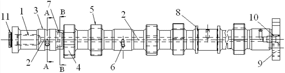
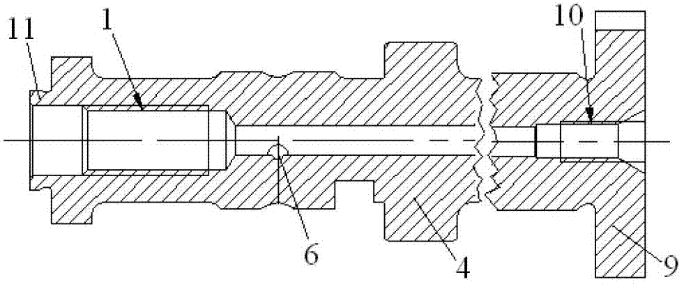
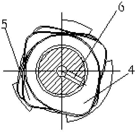
[0014] The structure and principle of the present invention will be further described below in conjunction with the accompanying drawings and through specific embodiments. Camshaft with code disc and lubricating oil channel, its structure is that the camshaft is a hollow shaft, an internal thread section 1 is arranged in the shaft center of the leftmost end of the camshaft, and the shaft at the end of the camshaft is behind the internal thread section The center is used as lubricating oil passage 2, and the camshaft is provided with supporting journal section 3, intake cam 4 and exhaust cam 5 in sequence (such as figure 1 , figure 2 ). Each bearing journal section is provided with oil inlet and outlet ports 6 (such as image 3 ), there is a timing plane 7 between the first bearing journal section at the left end of the camshaft and the intake cam (such as Figure 4 ), an axial thrust surface 8 is provided behind the second exhaust cam from the left of the camshaft, a gas d...


PUM


Abstract

The invention discloses a cam shaft with an encoding disk and a lubricating oil channel. The cam shaft is a hollow shaft; an inner thread section is arranged in a shaft center of the left end of the cam shaft; and a part from the tail end of the inner thread section to the shaft center at the tail end of the cam shaft is used as the lubricating oil channel. The cam shaft is sequentially provided with bearing shaft neck sections, air inlet cams, and air outlet cams; each bearing shaft neck section is provided with an oil inlet. A timing plane is arranged between a first bearing shaft neck section and the air inlet cam; an axial thrust surface is arranged behind a second air outlet cam shaft; the tail end of the cam shaft is provided with an air distribution timing encoding disk; and a lubricating oil channel sealing screw hole is formed in the shaft center of the tail end of the cam shaft. The cam shaft is provided with the timing plane, the thrust surface and the air distribution timing encoding disk, so that the problems of large number of auxiliary drive parts of an engine, and deformation caused by insufficient rigidity of an air distribution mechanism can be improved greatly; and the structure of the engine is simplified, the overall dimension of the engine is reduced, and convenience is brought to the decoration and arrangement of a finished automobile.

Description

technical field [0001] The invention belongs to the structural technology of an internal combustion engine, and in particular relates to a camshaft. technical background [0002] With the increasingly stringent emission requirements for motor vehicles in various countries in the world, electronically controlled engines have taken the main position, and the problem that arises is that the structural layout of the engine is more complicated. While improving the power of the engine, how to make the engine compact, reduce the size and save fuel has become the goal pursued by the engine industry. [0003] The existing camshaft structure mainly includes bearing journals, cams, connecting shafts, bolt holes, top holes, timing pin holes, etc. The camshaft obtains power from the engine crankshaft through gears, belts or sprockets, etc., and through the camshaft Rotation to drive the opening and closing of the valve. At present, most of the camshafts are arranged in the bottom type....

Claims


Application Information

Patent Timeline
IPC IPC(8): F01L1/047
Inventor 陈玉荣李晓刚张宏辉赵霄鹏张学存乌永波李长水张俊波蔡旭冰
Owner 东风朝阳朝柴动力有限公司
Why Eureka
Try Eureka