Laser ultrasonic detection device

A laser ultrasonic and detection device technology, which is applied in measuring devices, material analysis using sound waves/ultrasonic waves/infrasonic waves, and material analysis through optical means, can solve problems such as poor detection accuracy, and achieve fast scanning speed and practicality Strong, high detection efficiency

Inactive Publication Date: 2012-10-17
ACAD OF OPTO ELECTRONICS CHINESE ACAD OF SCI +1
View PDF6 Cites 21 Cited by
  • Summary
  • Abstract
  • Description
  • Claims
  • Application Information

AI Technical Summary

Problems solved by technology

The laser ultrasonic testing devices required by the above-mentioned patents must rotate the pipeline or move the detection device to dete

Method used


Image

  • Laser ultrasonic detection device
  • Laser ultrasonic detection device
  • Laser ultrasonic detection device

Examples


Embodiment 1

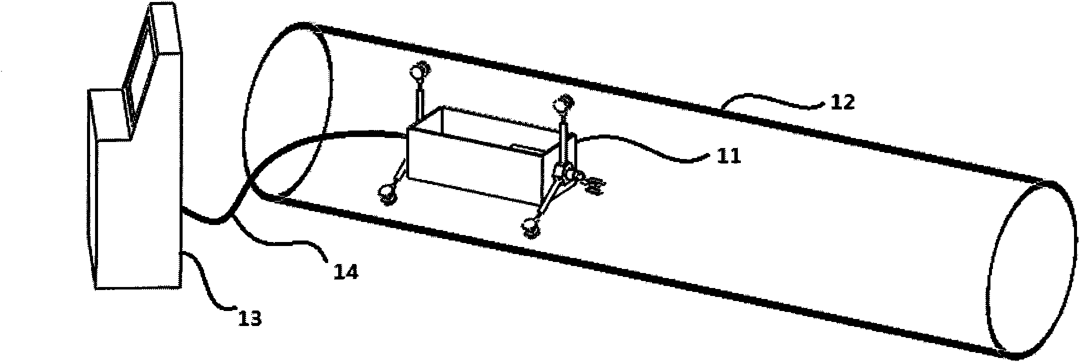
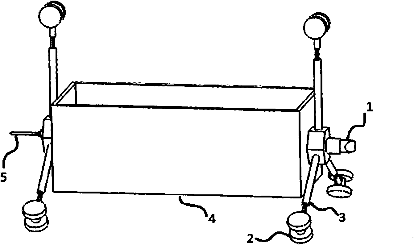
[0024] According to the instructions, make a set of laser ultrasonic detection device of the present invention, which device includes crawling car 11, optical fiber 14, external console 13, such as figure 1 shown. The external console 13 includes laser ultrasonic excitation source, control system circuit, control system software, display and other components. The crawling trolley 11 includes 6 sets of rotating scanning head 1, roller 2 and telescopic pole 3, a box body 4, and a communication optical interface 5, such as figure 2 shown. Wherein there are 6 sets of rollers 2 and telescopic poles 3, which are divided into two groups and fixed on both sides of the crawling trolley 11, with 3 sets in each group. The crawling trolley 11 is also equipped with a storage battery as a power source to provide power for the crawling trolley 11 . The crawling car 11 and the external console 13 exchange data through the optical fiber 14, and the exchanged data includes controlling the r...

Embodiment 2

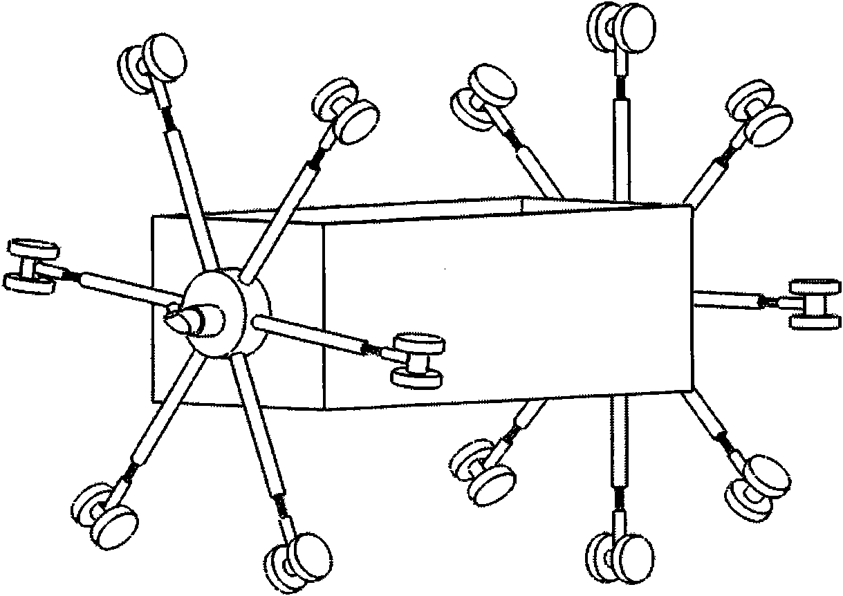
[0027] According to the instructions, a set of laser ultrasonic testing device of the present invention is made, which includes a crawling trolley 11, an optical fiber 14, and an external console 13. Wherein the external console 13 includes control system circuit, control system software, display and other components. The crawling trolley 11 includes a rotating scanning head 1, a total of 14 rollers 2 and telescopic poles 3, a box body 4, and a communication light interface 5, such as image 3 shown. Among them, there are 14 sets of rollers 2 and telescopic poles 3, which are divided into two groups and fixed on both sides of the crawling trolley 11. There are 6 sets on one side of the rotating scanning head 1 and 8 sets on the other side. The lengths of these telescopic poles are different. Can adjust the length, suitable for round, oval and rectangular pipes. The crawling trolley 11 is also equipped with a laser ultrasonic excitation source and a storage battery as a power...


PUM


Abstract

The invention relates to a laser ultrasonic detection device and belongs to the technical field of laser ultrasonic detection. The device is composed of a crawling trolley, an optical fiber and an external control console, wherein the crawling trolley comprises a rotational scanning head, rolling wheels and stretching supporting bars, a box body and a fiber interface. A laser ultrasonic excitation source, a laser interference detection system and a data process system can be carried on the crawling trolley. Ultrasound is excited to generate on detected surfaces by lasers led into the trolley by the optical fiber or emitted by the laser ultrasonic excitation source carried on the crawling trolley. Ultrasonic signals are detected by the laser interference detection system carried on the crawling trolley and data are transmitted to the external control console for display by the data process system. The external control console is capable of monitoring the states of the trolley and controlling the trolley to conduct detection. The device of the invention is capable of conducting laser ultrasonic detection to pipelines on the problems of inwall surface damages, defects inside pipeline walls and the like. The device also has fast surface-scanning speed and high detection efficiency and is very practical.

Description

technical field [0001] The invention relates to a novel laser ultrasonic testing device, in particular to a device for crawling inside a pipeline to perform laser ultrasonic testing of pipeline welds or defects, belonging to the technical field of laser ultrasonic testing. Background technique [0002] Laser ultrasonic testing technology is a non-destructive testing technology that uses lasers to excite and detect ultrasound. Compared with traditional piezoelectric ultrasonic technology, laser ultrasonic testing technology has the advantages of non-contact, broadband, and point emission and reception. Therefore, it can be used in material characterization, defect detection, process monitoring, and detection or monitoring of workpieces with complex shapes or equipment in special environments such as high temperature, high pressure, corrosion, and radiation. [0003] The laser ultrasonic detection system includes a laser ultrasonic excitation source and a detection system. Th...

Claims


Application Information

Patent Timeline
IPC IPC(8): G01N21/17G01N29/265
Inventor 赵天卓樊仲维余锦麻云凤刘洋张雪
Owner ACAD OF OPTO ELECTRONICS CHINESE ACAD OF SCI
Why Eureka
Try Eureka