Particle field transient multi-picture holography device and method

A technology of holography and particle field, applied in the field of holography, which can solve the problems of difficult adjustment of the optical path and low time resolution, etc.

Inactive Publication Date: 2014-12-31
INST OF FLUID PHYSICS CHINA ACAD OF ENG PHYSICS
View PDF4 Cites 1 Cited by
  • Summary
  • Abstract
  • Description
  • Claims
  • Application Information

AI Technical Summary

Problems solved by technology

[0006] The technical problem to be solved by the present invention is to propose a particle field transient multi-frame hologram based on photopolymer for the problems of difficult optical path adjustment and low time resolution in the above-mentioned existing particle field transient multi-frame holography technology. Camera device and method

Method used


Image

  • Particle field transient multi-picture holography device and method
  • Particle field transient multi-picture holography device and method
  • Particle field transient multi-picture holography device and method

Examples


Embodiment 1

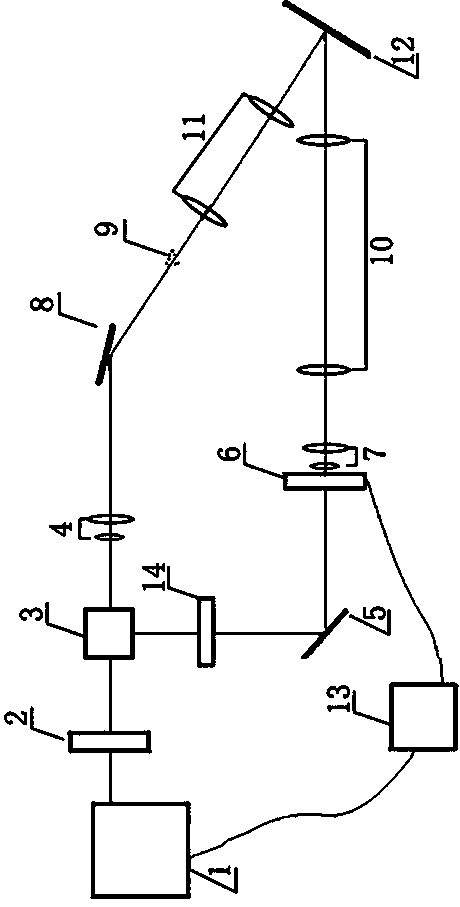
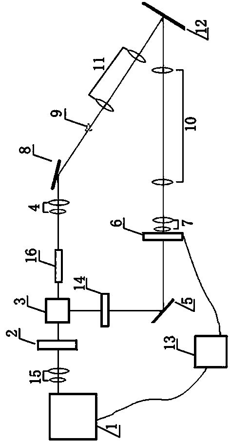
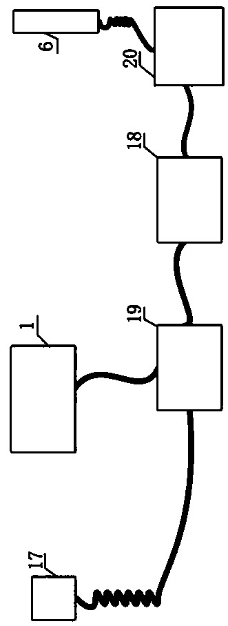
[0063] Embodiment 1, the device includes a coherent light generating device, an object light adjusting device, a reference light adjusting device, a synchronization control device 13 , and a holographic dry plate 12 . The coherent light generating device is used to receive the trigger signal of the synchronous control device 13 and generate laser pulses and divide it into two beams of coherent light; the object light adjusting device is used to introduce one of the two beams of coherent light generated by the coherent light generating device into The observation area 9 is used to provide backlighting for the observation area 9, and the beam of light becomes object light after passing through the observation area 9; the synchronous control device 13 is used to provide control signals to the coherent light generation device and the reference light adjustment device respectively; the reference light adjustment The device is used to adjust the angle and polarization state of anothe...

Embodiment 2

[0064] Embodiment 2. On the basis of Embodiment 1, the coherent light generating device includes a laser 1 and a beam splitting device 3 . The laser 1 is used to generate laser pulses according to the control signal output by the synchronous control device 13; the beam splitter 3 is used to divide the pulse signal generated by the laser 1 into two beams of coherent light and input them to the object light adjustment device and the reference light adjustment device respectively. , wherein the power ratio of one path of light input by the beam splitting device 3 to the object light adjusting device and the other path of light input by the beam splitting device 3 to the reference light adjusting device is 1:2-1:30.

[0065] Preferably, the power ratio of one path of light input by the beam splitting device 3 to the object light adjusting device and the other path of light input by the beam splitting device 3 to the reference light adjusting device is 1:4.

Embodiment 3

[0066] Embodiment 3, on the basis of Embodiment 1 or 2, the object light adjustment device includes a first beam expander collimator 4 and a second reflector 8, wherein the first beam expander collimator 4 is used to generate the interference light generating device The diameter of the coherent light spot of one channel is enlarged; the second reflector 8 is used to reflect the object light of the first beam expander and collimator 4 to the observation area 9, forming Plate object optics.

[0067] Preferably, the magnification of the first beam expander and collimator 4 is 10 to 40 times.


PUM


Abstract

The invention relates to the field of holography, particularly a particle field transient multi-picture holography device and a particle field transient multi-picture holography method. Aiming at the situation that multi-picture continuous particle field transient holography cannot be carried out in the prior art, the invention provides the particle field transient multi-picture holography device and the particle field transient multi-picture holography method based on a photo-induced polymer. The device comprises a coherent light generating device, an object light regulating device, a reference light regulating device, a synchronization control device, a holographic plate and the like. The method provided by the invention comprises the following steps that the synchronization control device is used to detect the particle field and send signals to the coherent light generating device and a light beam deflection device; the coherent light generating device generates two paths of coherent light according to the signals; one path of the coherent light forms the object light with the particle field information through the object light regulating device; the other path of coherent light forms the reference light through the reference light regulating device; the object light and the reference light form interference fringe on the holographic plate to be recorded by a photo-induced holographic plate. The device can be applied to the field of holography.

Description

Technical field [0001] The invention involves the field of holographic photography, especially the multiple holographic photography devices and methods of a particle field. Background technique [0002] Holographic has long been used in a single shot of particles and fluid fields, and has made great contributions to these fields.Its non -contact, large field of view, depth of field, and three -dimensional appear have unique advantages in the field of particle field diagnosis.The detection of particle fields using holography usually includes three links: record, development and reproduction.Records mainly refer to the two light beams divided by the pulse laser on the same pulse on the surface of the recording medium (holographic dry plate).In the two beams of light, one beam with a particle field information (material light), and the other bundle without particle field information (reference light).The development is mainly for the three types of materials of halogen silver latex,...

Claims


Application Information

Patent Timeline
Patent Type & Authority Patents(China)
IPC IPC(8): G01N21/45G03H1/10
Inventor 李泽仁赵宇李作友罗振雄刘振清蒙建华李军叶雁朱鹏飞魏明宾
Owner INST OF FLUID PHYSICS CHINA ACAD OF ENG PHYSICS
Why Eureka
Try Eureka