Rotary table structure and machine tool

A technology of rotary worktable and worktable, applied in metal processing machinery parts, metal processing, manufacturing tools, etc., can solve the problems of high cost, easy deformation, difficult processing of sheet hoop, etc., and achieve high positioning accuracy and clamping. High torque, saving installation space

Inactive Publication Date: 2012-10-24
SHANGHAI SANY PRECISION MACHINERY
View PDF4 Cites 14 Cited by
  • Summary
  • Abstract
  • Description
  • Claims
  • Application Information

AI Technical Summary

Problems solved by technology

At present, the brake and locking of the rotary table are mostly realized by a sheet-type circular hoop. Such a hoop-type

Method used


Image

  • Rotary table structure and machine tool
  • Rotary table structure and machine tool
  • Rotary table structure and machine tool

Examples


Embodiment Construction

[0028] The present invention will be further described below in combination with principle diagrams and specific operation examples.

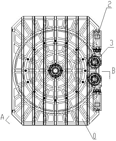
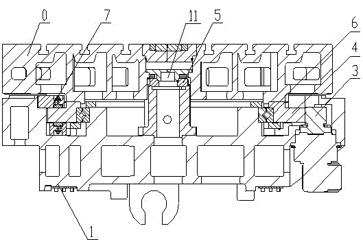
[0029] figure 1 and figure 2 Respectively show a top view of the rotary table structure according to a preferred embodiment of the present invention and a cross-sectional view along A-base circular table center-B in the top view, as shown in the figure, the rotary table structure in the embodiment of the present invention Including workbench 0 and base 1, the middle part of base 1 has base circular platform 11, the rotary workbench in the embodiment of the present invention is mainly composed of two sets of servo motors 2, two reducers, two driving gears 3, driven gear 4, piston Clamping mechanism 7, angle encoder 5 and cross roller bearing 6 are composed.

[0030] In the preferred embodiment of the present invention, the cross roller bearing 6 is used as the turning and bearing mechanism of the turning table. The characteristics of the cro...


PUM


Abstract

The invention discloses a rotary table structure and a machine tool, and belongs to the technical field of rotary tables. The rotary table structure mainly comprises two servo motors, two speed reducers, two driving gears, a driven gear, piston clamping mechanisms, an angle encoder and crossed roller bearings, the piston clamping mechanisms are symmetrically arranged on the upper side and the lower side of a gear ring of the driven gear, oil is fed into an oil cavity in each piston clamping mechanism after a table rotates for a required angle, upper pistons and lower pistons simultaneously clamp the driven gear, and braking and locking are carried out by the aid of friction force between each piston and a corresponding end surface of the driven gear. The rotary table structure is designed for small and medium machine tools, rotational stability and operational reliability of the table are realized by an anti-backlash effect of the piston clamping mechanisms and the double motors, and the rotary table structure is high in rotation precision and simple and compact in structure and is time-saving and labor-saving.

Description

technical field [0001] The invention relates to the technical field of a rotary table, in particular to a structure of a rotary table and a machine tool. Background technique [0002] With the rapid development of CNC machine tool technology, the demand for CNC rotary table is increasing, and the requirements for its rotary accuracy, work reliability, manufacturability, and low energy consumption are also getting higher and higher. Because the traditional sliding guide rail table is supported by the metal sliding guide rail surface as the rotating support, the friction coefficient of the metal sliding guide rail surface is relatively high, so the drive power is required to be large, it will generate heat, cannot rotate at a high speed, and consumes high energy consumption. At present, the static pressure rotary table is used more and more, but the structure of the static pressure guide rail is complex, the processing requirements are high, and the assembly process is also di...

Claims


Application Information

Patent Timeline
IPC IPC(8): B23Q1/64B23Q5/56B23Q5/36
Inventor 贾晓飞孟祥东李小龙
Owner SHANGHAI SANY PRECISION MACHINERY
Why Eureka
Try Eureka