fuel injector

A technology of fuel injectors and nozzles, which is applied in the direction of machines/engines, fuel injection devices, engine components, etc., and can solve problems such as many high-pressure leakage links, unsatisfactory pressure response speed, and complex structures

Inactive Publication Date: 2016-03-09
袁辉
View PDF5 Cites 0 Cited by
  • Summary
  • Abstract
  • Description
  • Claims
  • Application Information

AI Technical Summary

Problems solved by technology

[0006] The common feature of the above three methods is that the plunger for generating pressure and the oil nozzle for controlling fuel injection are set separately, and they are connected by oil passages or high-pressure oil pipes. method), the pressure response speed is not ideal, there are many high-pressure leakage links, and it is very difficult to further increase the pressure, etc.

Method used


Image

  • fuel injector
  • fuel injector
  • fuel injector

Examples


Embodiment Construction

[0027] This patent provides three embodiments.

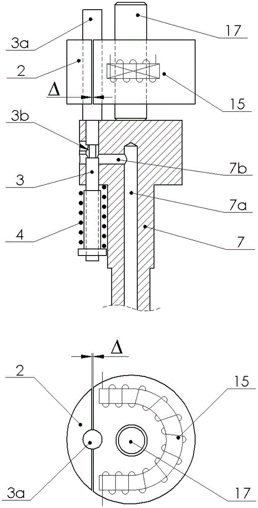
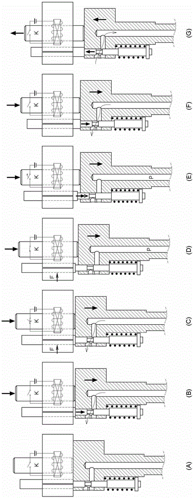
[0028] Figure 1~Figure 3 It is the first embodiment. In this embodiment, the plunger is installed in the inner hole of the needle valve of the oil nozzle, the fuel injection and the oil inlet into the high-pressure chamber are controlled by electric control, and the plunger is pushed by a mechanical method.

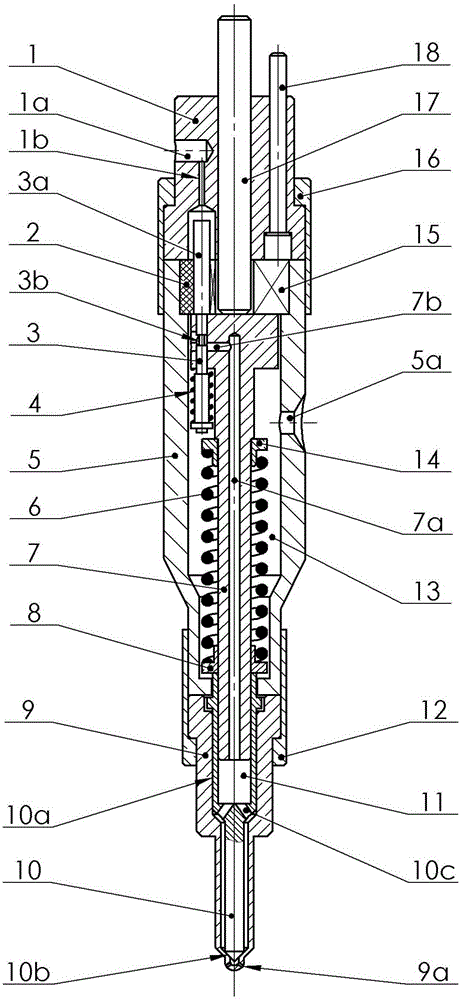
[0029] figure 1 As shown, same as the traditional injector, there are injector body (5), nozzle body (9), nozzle needle valve (10), pressure spring (6), nozzle tight cap (12) and nozzle body (9 ) nozzle hole (9a) on the head, the outer circle of the nozzle needle valve guide rod (10a) and the nozzle body (9) are in a precise sliding fit.

[0030] The oil nozzle needle valve guide rod (10a) has an inner hole in the axial direction, and a plunger (7) is installed in the inner hole. The plunger (7) and the inner hole of the oil nozzle needle valve (10) are in a precise sliding fit. ) and the nozzle needle valve (10) are mo...


PUM


Abstract

Provided is a fuel injector for a diesel engine. A plunger is arranged in the fuel injector, and the plunger and a fuel nozzle needle valve are combined into a pair of matching parts. The matching parts can be in a mode that the fuel nozzle needle valve is installed in an inner hole of the plunger or in a mode that the plunger is installed in an inner hole of the fuel nozzle needle valve. Fuel injection and fuel feeding of a high-pressure cavity can be controlled through an electric control method or a mechanical method. The plunger can be pushed through a mechanical method or a hydraulic method, wherein pressurizing injection can be further achieved by means of the hydraulic method. The fuel injector reduces volume of the high-pressure cavity and a leakage link furthest. Therefore, the fuel injector is quick in pressure building up, less in leakage amount, high in injection pressure, clean in discharged tail gas and low in fuel consumption. An electric control valve is not driven by an armature directly, and clearance between a solenoid valve and the armature can be smallest, so that miniaturization of the solenoid valve is facilitated.

Description

technical field [0001] The invention relates to a fuel injector for a diesel engine. Background technique [0002] Currently known fuel injectors for diesel engines, the nozzle needle valve only plays the role of cutting off fuel injection, and the plunger responsible for providing high-pressure diesel usually has the following three methods. [0003] 1. It is installed on a separate fuel injection pump. The fuel injection pump and the fuel injector are connected by high-pressure oil pipes. Typical representatives include traditional mechanical fuel injection pump-fuel injector systems, high-pressure common rail fuel injection systems, and single pumps. fuel injection system. [0004] 2. It is installed on the top of the injector, separated from the nozzle in the injector. The plunger and the nozzle are connected by a built-in oil passage, that is, the pump nozzle type fuel injection system. [0005] 3. It has the above two characteristics at the same time. The plunger in ...

Claims


Application Information

Patent Timeline
Patent Type & Authority Patents(China)
IPC IPC(8): F02M61/10F02M61/18F02M61/20F02M51/06
Inventor 袁辉
Owner 袁辉
Why Eureka
Try Eureka