Automatic differential pressure balance type valve position indicator

An automatic balance and indicator technology, applied in the direction of valve devices, engine components, mechanical equipment, etc., can solve the problems of non-operation of gears, high requirements for bearing type selection and quality, high tolerance and assembly requirements of gear seats and upper and lower connecting blocks, etc. Achieve the effects of reducing mechanical wear and running resistance, reducing processing technology and assembly accuracy requirements, and improving measurement accuracy and service life

Active Publication Date: 2012-10-24
汉盛(上海)海洋装备技术股份有限公司
View PDF4 Cites 1 Cited by
  • Summary
  • Abstract
  • Description
  • Claims
  • Application Information

AI Technical Summary

Problems solved by technology

Existing problems: 1. High machining accuracy requirements for measuring gears, gear seats, and transmission parts; 2. High requirements for shape and position tolerances such as coaxiality, flatness, and assembly of gear seats and upper and lower connecting blocks; 3. Due to the volume Restrictions have high requirements on the selection and quality of bearings; 4. High working pressure (generally 13.5MPa), resulting in high pressure difference between upstream and downstream, under the action of hydraulic pressure, the gear is pushed to the downstream side of the gear

Method used


Image

  • Automatic differential pressure balance type valve position indicator
  • Automatic differential pressure balance type valve position indicator
  • Automatic differential pressure balance type valve position indicator

Examples


Embodiment Construction

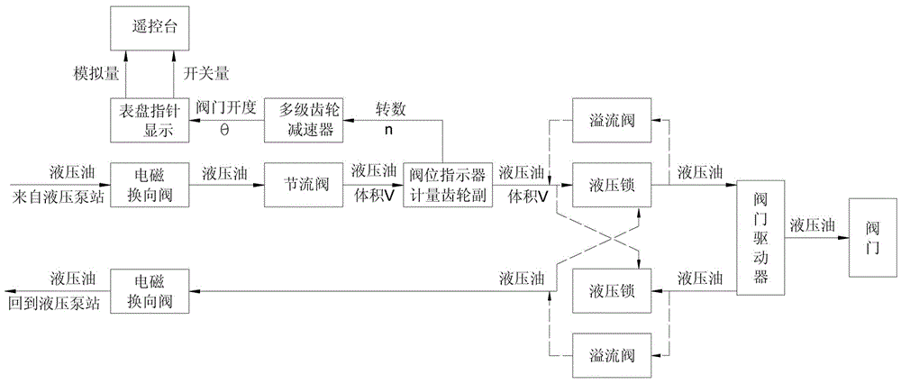
[0025] According to attached figure 1 , is the working principle diagram of the differential pressure automatic balance valve position indicator. The device includes electromagnetic reversing valve, throttle valve, differential pressure automatic balance valve position indicator, hydraulic lock, overflow valve, hydraulic driver, valve, pressure oil pipe, electrical interface, etc.

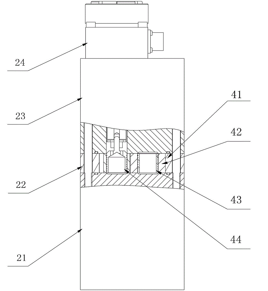
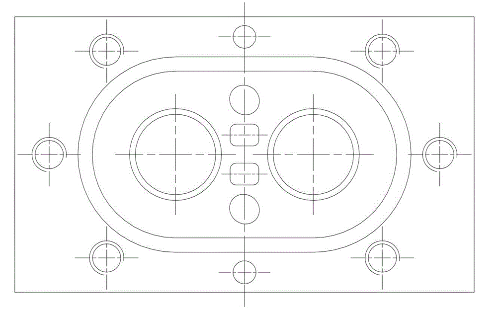
[0026] The hydraulic oil from the power pump station enters the oil inlet cavity of the metering gear pair 22 of the pressure difference automatic balance valve position indicator after passing through the electromagnetic reversing valve and the throttle valve to adjust the flow rate, and drives a pair of metering gears 42 to rotate. In this way, the volumetric flow measurement is realized, and the measured hydraulic oil is then sent to the valve driver through the hydraulic lock. The low-pressure hydraulic oil at the oil return port of the valve driver passes through the hydraulic lock, and then ...


PUM


Abstract

The invention relates to an automatic differential pressure balance type valve position indicator, which is mounted on a hydraulic circuit of a valve driver and comprises a valve seat 21, a metering gear pair 22, a meter head seat 23 and a meter head 24. The automatic differential pressure balance type valve position indicator is characterized in that the metering gear pair 22 consists of a pair of metering gears 42, a first gear bushing 43, a second gear bushing 44 and a metering gear seat 41, wherein the first gear bushing 43 and the second gear bushing 44 are arranged at the axle centers of the metering gears; pressure relief through holes are formed in tooth roots of each metering gear 42 in an equidistantly-staggered manner; a pressure relief passage is formed after the first gear bushing 43 and one metering gear 42 are assembled, and after the second gear bushing 44 and the other metering gear 42 are assembled, not only is an oil draining passage formed, but also the mechanical transmission without transmission shafts, fixing shafts and bearings is realized; and one end, where gear oil chambers are located, of the metering gear seat 41 is designed into an outline of two-circle intersecting, so that the smoothness of operation of the pair of metering gears 42 in two intersecting circles is favored.

Description

technical field [0001] The invention relates to a hydraulic valve remote control system used for ships and marine equipment, and in particular discloses a differential pressure automatic balance valve position indicator, which is used to control the opening of the valve during the remote control of the valve. Devices for indication and status measurement. Background technique [0002] At present, only low-end products are available in domestic hydraulic valve position indicators. The measurement principle adopted by foreign advanced hydraulic valve position indicators is volumetric, and the measuring element is a pair of high-precision cylindrical gears with the same modulus and the same number of teeth. The gear transmission mode is the fixed bearing type at both ends of the shaft. Existing problems: 1. High machining accuracy requirements for measuring gears, gear seats, and transmission parts; 2. High requirements for shape and position tolerances such as coaxiality, fla...

Claims


Application Information

Patent Timeline
IPC IPC(8): F16K37/00
Inventor 顾耀民陈亚军李军华王维彬
Owner 汉盛(上海)海洋装备技术股份有限公司
Why Eureka
Try Eureka