Flexible heat-transfer device based on low-melting metal joints

A low-melting-point metal and joint technology, applied in the direction of indirect heat exchangers, heat exchange equipment, semiconductor devices, etc., can solve the problems of limiting the bending flexibility of flexible pipe sections, large contact thermal resistance, and easy failure of heat pipes, etc., to achieve easy implementation , Small thermal contact resistance, high thermal conductivity

Inactive Publication Date: 2012-10-24
TECHNICAL INST OF PHYSICS & CHEMISTRY - CHINESE ACAD OF SCI
View PDF5 Cites 16 Cited by
  • Summary
  • Abstract
  • Description
  • Claims
  • Application Information

AI Technical Summary

Problems solved by technology

However, the heat conduction through the hinge is solid-solid heat conduction, the contact thermal resistance is large, and the heat transfer efficiency is low
Moreover, the hinge can only achieve one degree of freedom of rotation along the center line, and the flexibility is relatively poor
[0004] Generally speaking, the above-mentioned flexible heat conduction device has the following disadvantages: (1) The flexible pipe part of the flexible heat pipe must be arranged with a ca

Method used


Image

  • Flexible heat-transfer device based on low-melting metal joints
  • Flexible heat-transfer device based on low-melting metal joints
  • Flexible heat-transfer device based on low-melting metal joints

Examples


Embodiment 1

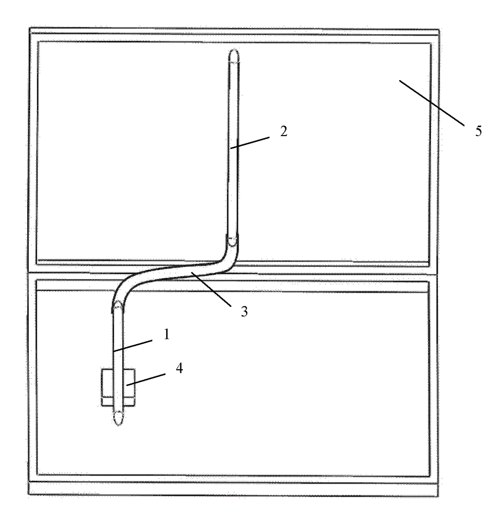
[0022] The flexible heat conduction device based on the low-melting-point metal joint provided by the invention can be used for heat dissipation of electronic devices such as notebook computers and mobile phones. figure 2 It shows the structural representation of the low-melting point metal flexible heat conduction device that conducts the heat from the CPU of the laptop to the LCD backplane for heat dissipation.

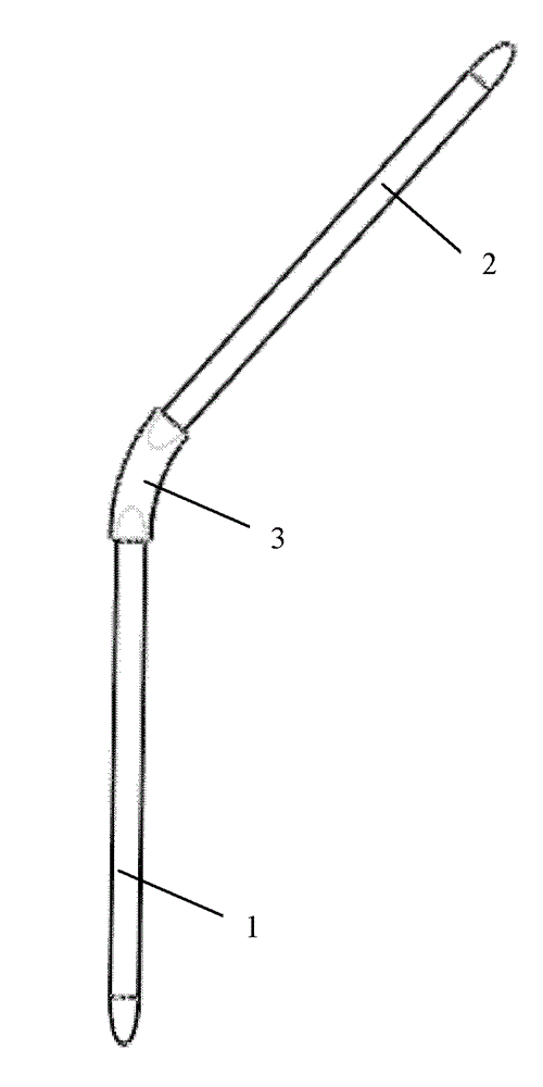
[0023] Depend on figure 1 It can be seen that the flexible heat conduction device based on low-melting-point metal joints of the present invention is composed of N flexible pipe-type liquid metal joints and (N+1) heat pipes; said N is a positive integer of 1 to 10, and said heat pipes It is connected to both ends of the flexible pipe type liquid metal joint; the pipe of the flexible pipe type liquid metal joint stores low melting point metal which is liquid at room temperature.

[0024] figure 1 In the shown embodiment, N=1, that is, the flexible heat conduction ...

Embodiment 2

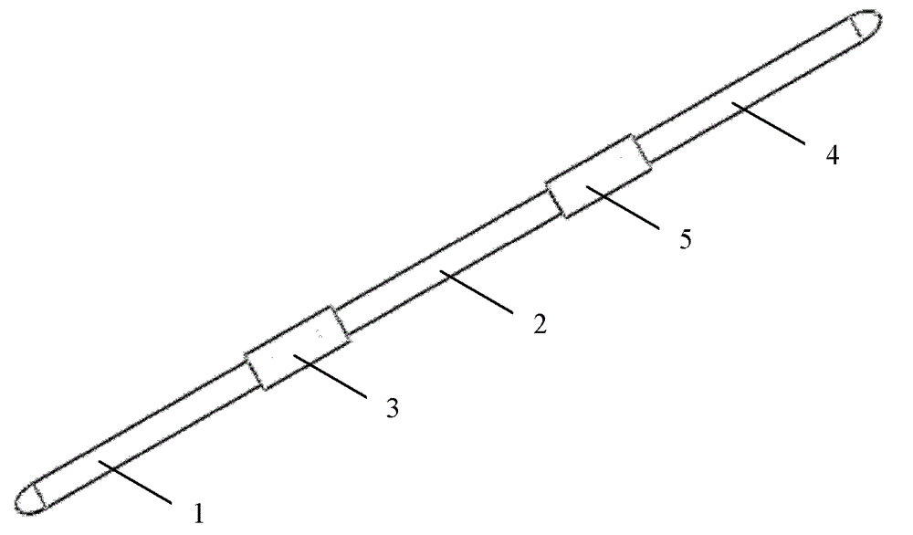
[0032] Such as image 3 As shown, the flexible heat conduction device based on the low-melting point metal joint provided by the present invention can be cascaded sequentially to form a multi-stage flexible heat conduction device with multiple heat pipes and multiple flexible pipeline liquid metal joints; the multi-stage flexible heat conduction device can realize More flexible arrangement and bending.

[0033] N=2 in this embodiment, that is: three heat pipes (the first heat pipe 1, the second heat pipe 2, the third heat pipe 4) and two flexible pipe type liquid metal joints (the first flexible pipe type liquid metal joint 3, the second Flexible pipe type liquid metal joint 5); the first heat pipe 1, the first flexible pipe type liquid metal joint 3, the second heat pipe 2, the second flexible pipe type liquid metal joint 5 and the third heat pipe 4 are sequentially connected to form a three-stage type Flexible heat conduction device.

[0034] Both the pipes of the first fl...


PUM

PropertyMeasurementUnit
Melting pointaaaaaaaaaa

Abstract

A flexible heat-transfer device based on low-melting metal joints consists of N flexible pipeline type liquid metal joints and N+1 heat pipes; N is a positive integral between 1 and 9; the heat pipes are communicated with both ends of the flexible pipeline type liquid metal joints; low-melting metal which has high heat conductivity and is liquid at room temperature is stored in the flexible pipeline type liquid metal joints; in the running process, heat passes through the heat pipes and the flexible pipeline type liquid metal joints arranged at intervals in sequence so as to realize the heat transfer. The low-melting metal has high heat conductivity so that the device can realize high-efficient heat transfer property; simultaneously, the connection by the flexible liquid metal can guarantee the flexible bending of the whole heat-transfer device; and the flexible heat-transfer device has the advantages of simple structure, excellent heat-conducting property and high bending flexibility, and can be applied to the fields of aerospace heat management and IT (Information Technology) such as notebook computer, mobile phone and server.

Description

technical field [0001] The invention relates to a heat conduction device, in particular to a flexible heat conduction device based on low melting point metal joints. Background technique [0002] Flexible heat conduction devices are generally used in occasions where there is relative movement at both ends of the heat transfer. For example, when a space satellite is in operation, there is mechanical vibration or movement between some heating elements and the radiation plate, so a flexible heat pipe is required to realize heat conduction (CN 200610063418.2). A flexible heat pipe generally consists of a flexible pipe connecting two rigid pipes. In order to ensure the free return of condensed liquid, the capillary structure and support structure must be arranged in the flexible pipe. However, the capillary structure greatly limits the bending flexibility of the pipe, and when the bending degree is greater than 90 degrees, it is easy to cause difficulty in liquid reflux and eve...

Claims


Application Information

Patent Timeline
IPC IPC(8): F28D15/04F28F21/08F28F21/06H01L23/427G06F1/20
Inventor 邓月光刘静
Owner TECHNICAL INST OF PHYSICS & CHEMISTRY - CHINESE ACAD OF SCI
Why Eureka
Try Eureka