Optical remote sensing image change detection based on image fusion
What is AI technical title?
AI technical title is built by PatSnap AI team. It summarizes the technical point description of the patent document.
An optical remote sensing image, change detection technology, applied in the field of image processing, can solve the problems of exaggeration, false changes, large differences, etc., to achieve the effect of enhancing change information, high detection accuracy, and suppressing background information
Inactive Publication Date: 2012-10-24
XIDIAN UNIV
View PDF2 Cites 26 Cited by
Summary
Abstract
Description
Claims
Application Information
AI Technical Summary
This helps you quickly interpret patents by identifying the three key elements:
Problems solved by technology
Method used
Benefits of technology
Problems solved by technology
[0004] Although the two change detection methods using the difference method to construct the difference map and the ratio method to construct the difference map can effectively detect the change information of the optical remote sensing image, these two methods still have their own shortcomings: the difference method is easily affected by the image Influenced by objective conditions such as imaging quality and spectral characteristics, it is easy to produce "false change" information; it cannot fully reflect the change of radiation energy of ground objects, such as the change of gray value from 50 to 30 and 250 to 220, and the energy change of the corresponding position on the ground They are not equivalent, and cannot be treated equally; in addition, when using the difference map constructed by the difference method to detect changes in optical remote sensing images, the detection result has a high rate of missed detection
The image ratio method can help reduce the influence of atmospheric conditions while enhancing the change information and suppressing the background information, but sometimes it will over exaggerate some changes, such as the change of the gray value from 200 to 20 and from 20 to 10, the ratio method cannot be distinguished, but the difference obtained by the difference method is very large; in addition, when using the difference image constructed by the ratio method to detect changes in optical remote sensing images, the detection results have a high false detection rate
Method used
Image
Click on the blue label to locate the original text in one second.
Reading with bidirectional positioning of images and text.
Examples
Embodiment 1
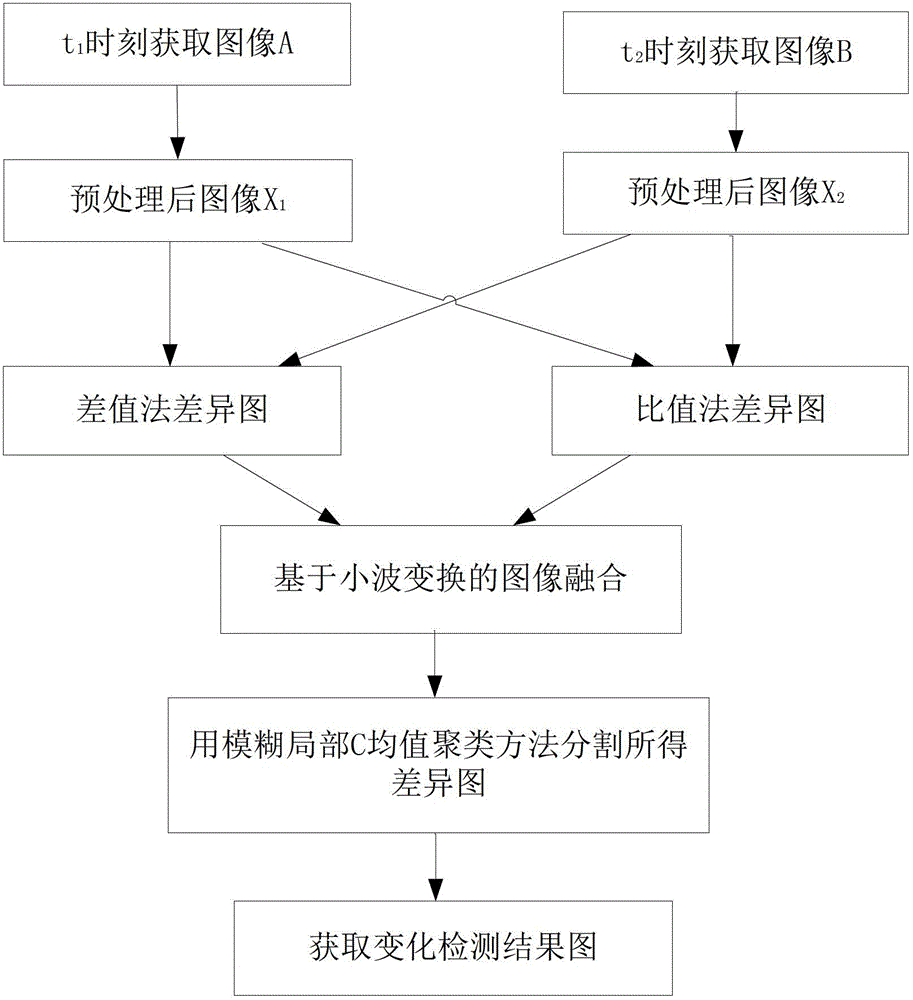
[0029] refer to figure 1 , the implementation steps of this example are as follows:
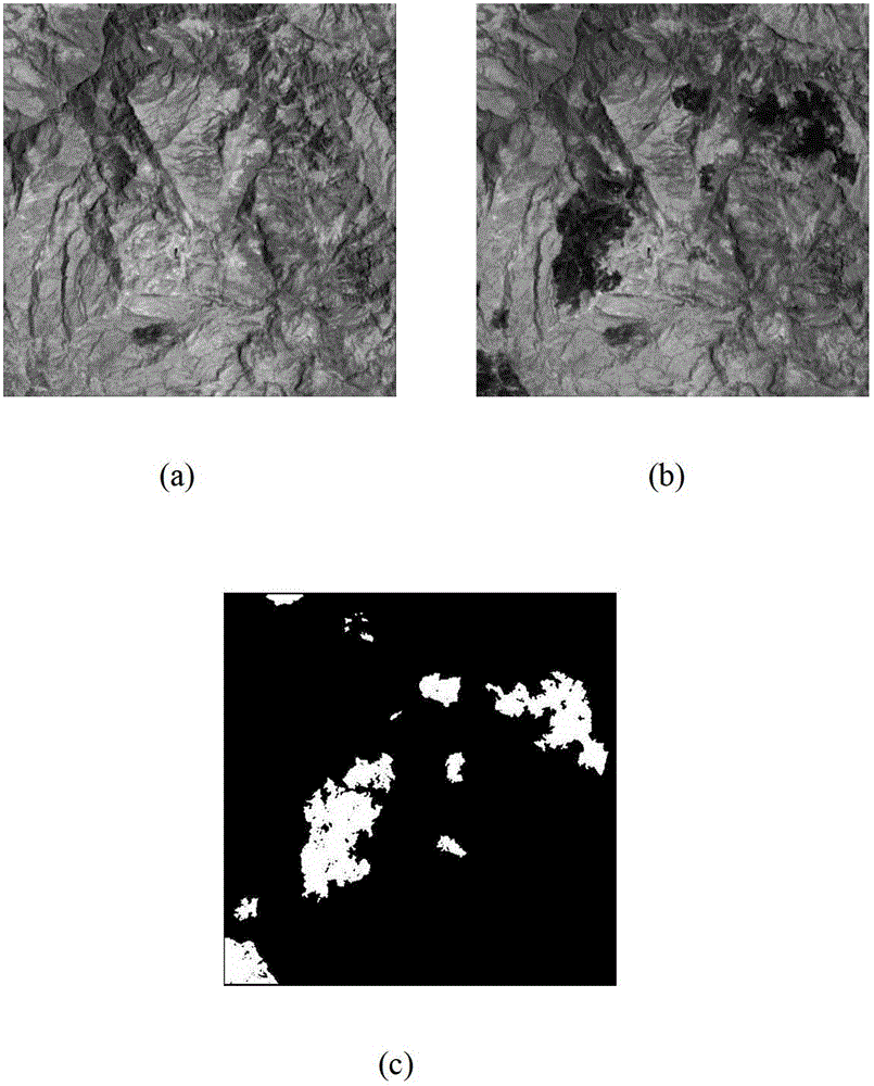
[0030] Step 1: Acquire two optical remote sensing images at different times in the same region of Mexico, filter and denoise the two optical remote sensing images, preprocess radiation correction and geometric registration, and obtain two processed images X 1 ,X 2 , where the image X obtained after preprocessing 1 like image 3 As shown in (a), the image X obtained after preprocessing 2 like image 3 (b) shown.
[0031] The geometric error of the image can be eliminated through preprocessing, so as to match the geographical coordinates of different images in the same area, and eliminate the noise caused by the sensor itself and the radiationnoise caused by atmospheric radiation.
[0032] Step 2, use the preprocessed two images X 1 ,X 2 , respectively constructing difference method difference map X D and ratio method difference chart X R .
[0033] (2.1) will be as image 3 Image ...
Embodiment 2
[0054] refer to figure 1 and figure 2 , the implementation steps of this example are as follows:
[0055] Step 1: Filter and denoise the two optical remote sensing images acquired at different times in the same area, that is, the Sardinia region of Italy, perform preprocessing of radiometric correction and geometric registration, and obtain two processed images X′ 1 ,X′ 2 , where the preprocessed image X′ 1 like Image 6 As shown in (a), the image X′ obtained after preprocessing 2 like Image 6 (b) shown.
[0056] Step 2, using the preprocessed Image 6 The image X' shown in (a) 1 and Image 6 The image X' shown in (b) 2 , using the difference operation to construct such as Figure 7 (a) The difference method difference graph X' shown in (a) D , using the ratio operation to construct such as Figure 7 (b) shows the ratio method difference diagram X' R , the specific implementation steps are as step 2 in embodiment 1.
[0057] Step three, for example Figure 7 ...
PUM
Abstract
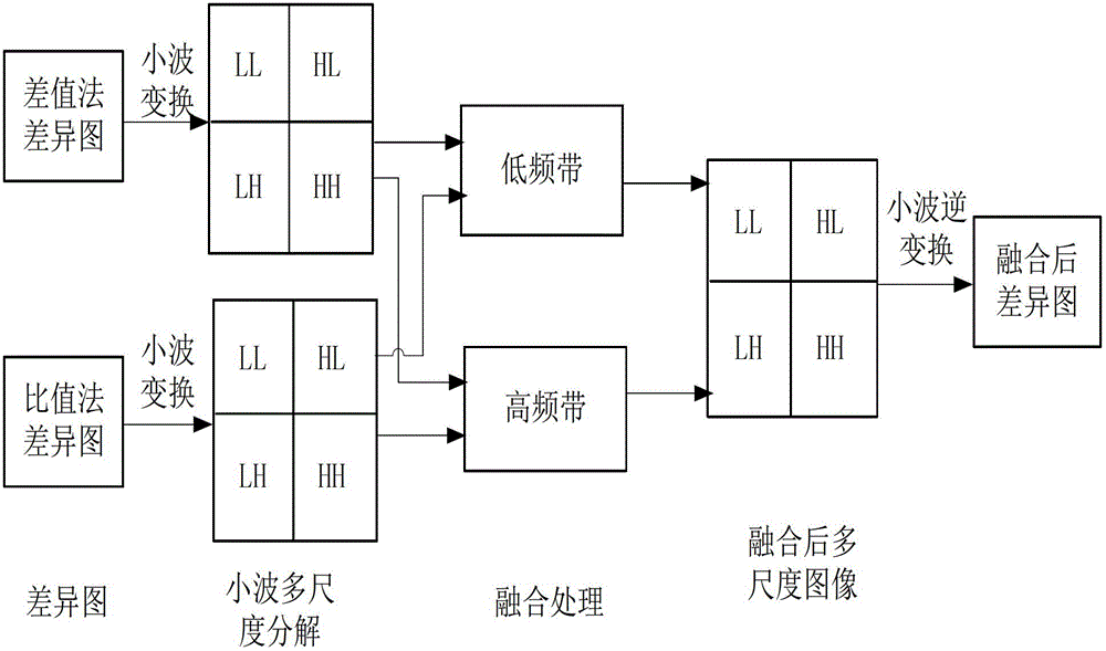
The invention discloses an optical remote sensing image change detection method based on image fusion, and mainly solves the problem of low detection result precision of the existing change detection technology. The optical remote sensing image change detection method comprises the following steps: respectively constructing a difference method difference graph and a ratio method difference graph after two optical remote sensing images which are acquired in the same region at different time points are preprocessed; respectively performing N-layer waveletdecomposition on the two difference graphs to acquire wavelet coefficients of a high-frequency band and a low-frequency band of each decomposition layer; performing fusion processing on the wavelet coefficients of the high-frequency band and the low-frequency band by using different fusion operators to obtain fusion wavelet coefficients of the high-frequency band and the low-frequency band; performing inverse transformation on the fusion wavelet coefficients of the high-frequency band and the low-frequency band to obtain a fused difference graph; and partitioning the fused difference graph by using a blurring partial C-mean-value clustering method to obtain a change detection result. According to the invention, the difference graph performance of the optical remote sensing image is improved, so that the precision of the detection result is improved; and the method can be used for natural disaster evaluation and environment detection.
Description
technical field [0001] The invention belongs to the field of image processing and relates to the change detection of optical remote sensing images, which can be used in dynamic detection of lake water levels in environmental changes, dynamic detection of crop growth status, military reconnaissance, natural disaster assessment and many other fields to improve the detection results of changes in optical remote sensing images the accuracy. Background technique [0002] The change detection technology of remote sensing images is an important part of remote sensing image research. It compares and analyzes multi-temporal remote sensing images obtained at different times in the same area, and obtains the required features or targets over time according to the differences between images. change information. Change detection technology can detect the changes between the image gray value or local texture in different periods, and on this basis, the changes in shape, position, quantit...
Claims
Application Information
Patent Timeline
Application Date:The date an application was filed.
Publication Date:The date a patent or application was officially published.
First Publication Date:The earliest publication date of a patent with the same application number.
Issue Date:Publication date of the patent grant document.
PCT Entry Date:The Entry date of PCT National Phase.
Estimated Expiry Date:The statutory expiry date of a patent right according to the Patent Law, and it is the longest term of protection that the patent right can achieve without the termination of the patent right due to other reasons(Term extension factor has been taken into account ).
Invalid Date:Actual expiry date is based on effective date or publication date of legal transaction data of invalid patent.

