
Method for determining initial position angle of rotor of permanent-magnetic synchronous motor

A permanent magnet synchronous motor, rotor initial position technology, applied in the control of generator, motor generator control, control of electromechanical transmission and other directions, can solve the problems of low precision, failure of motor start, complex processing steps, etc., to achieve high current Sampling accuracy, small possibility of misjudgment, and concise follow-up processing

Inactive Publication Date: 2012-10-24
SHANGHAI STEP ELECTRIC +1
View PDF2 Cites 27 Cited by
  • Summary
  • Abstract
  • Description
  • Claims
  • Application Information

AI Technical Summary

Problems solved by technology

In the permanent magnet synchronous motor vector control, the initial position of the rotor is a very important quantity. If the initial position is not estimated accurately, it may reverse when the motor starts or cause the motor to fail to start, and it may also affect the system after starting. running performance
Using the existing method for detecting the initial position of the rotor without an absolute position encoder has the defects of too complicated processing steps and low precision

Method used


Image

  • Method for determining initial position angle of rotor of permanent-magnetic synchronous motor
  • Method for determining initial position angle of rotor of permanent-magnetic synchronous motor
  • Method for determining initial position angle of rotor of permanent-magnetic synchronous motor

Examples


Embodiment Construction

[0021] The present invention will be further described below in conjunction with the accompanying drawings.

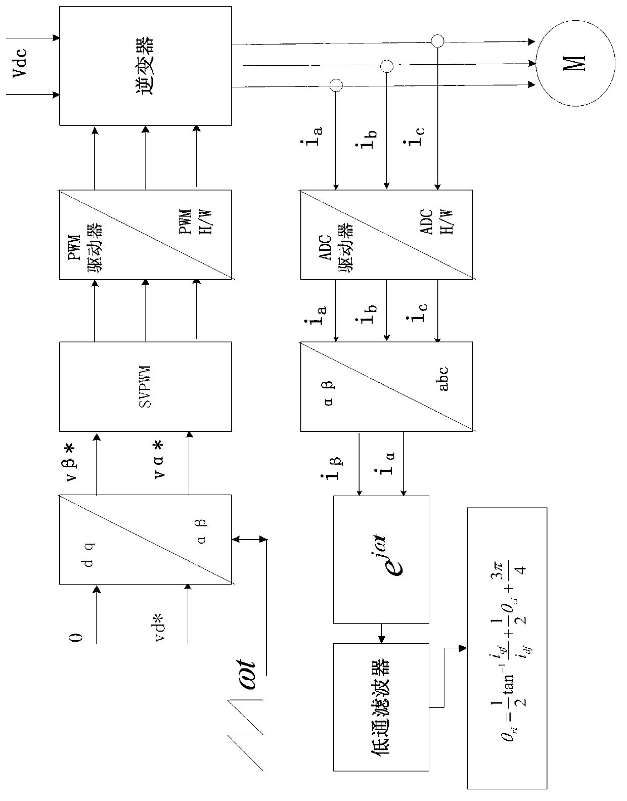
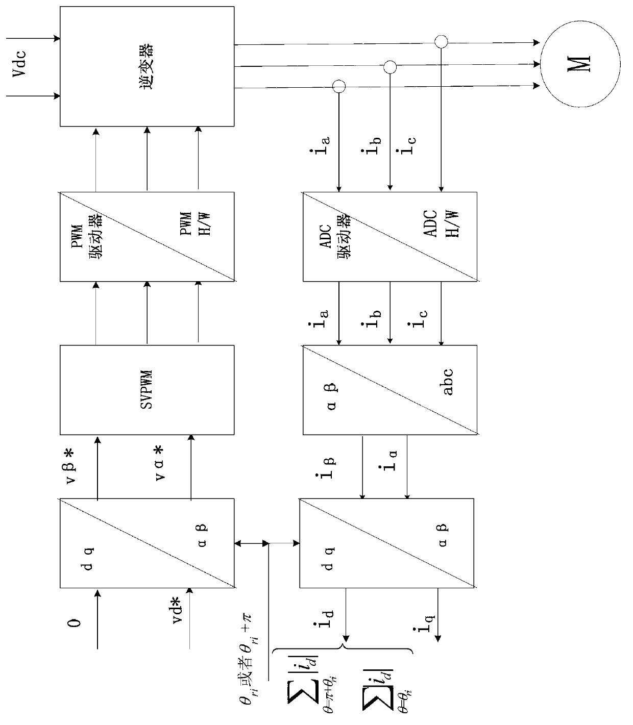
[0022] combined with figure 1 and figure 2 As shown, a method for determining the initial position angle of the rotor of a permanent magnet synchronous motor according to an embodiment of the present invention includes the following steps:

[0023] Step 1, inject amplitude U, angular frequency ω, and initial phase θ into the stator winding of the permanent magnet synchronous motor under test ci The high-frequency rotating voltage vector signal of the

[0024] The high-frequency torque generated by the high-frequency rotating voltage vector signal is not enough to make the measured permanent magnet synchronous motor rotate, so it can ensure that the motor is in a static state during the identification process; in addition, the injected high-frequency rotating voltage vector signal The angular frequency ω is much higher than the rated operating frequency of the tes...


PUM


Abstract

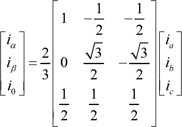
The invention discloses a method for determining an initial position angle of a rotor of a permanent-magnetic synchronous motor. The method comprises the steps of: inputting a high-frequency rotary voltage vector signal with an amplitude value as U, an angular frequency as omega and an initial phase position as thetaci to obtain an alpha-axis current ialpha and a beta-axis current ibeta; converting the ialpha and the ibeta into a coordinate which rotates synchronously for the angular frequency omega to obtain a d-axis current id and a q-axis iq; performing low-pass filtering on the id and iq to obtain Idf and Iqf; calculating a predicted value thetari of the initial position angle of the rotor by utilizing a formula; inputting a pulse voltage vector in the stator winding, wherein the angle is equal to thetari; obtaining the d-axis current and an integral under the action of the pulse voltage vector, thereby obtaining sigmaI0; after 3 ms-10 ms, inputting another pulse voltage vector to the stator winding, wherein the angle is equal to thetari plus 180 degrees; obtaining the d-axis current and an integral under the action of the other pulse voltage vector, thereby obtaining sigmaIpi; and comparing the absolute values of the sigmaI0 and the sigmaIpi, wherein if the absolute value of the sigmaIpi is greater than the absolute value of the sigmaIpi, the initial position angle of the rotor is equal to thetari; otherwise, the initial position angle of the rotor is equal to thetari plus 180 degrees. The method for determining the initial position angle of the rotor of the permanent-magnetic synchronous motor, disclosed by the invention, has the advantages of simple treatment process and high detection precision.

Description

technical field [0001] The invention relates to a method for determining the initial position angle of a rotor of a permanent magnet synchronous motor. Background technique [0002] In order to achieve high-precision and high-dynamic performance control of the speed and position of permanent magnet synchronous motors, accurate rotor position information is required. If the rotor position detection error is large, it will cause the motor to not start and run normally. At present, there are mainly two methods for rotor position detection: direct detection by position sensor and estimation of rotor position by position sensorless algorithm, but no matter which method is used, the initial position of the rotor needs to be judged in advance. Moreover, the detection of the initial position angle of the rotor magnetic pole is also the basic requirement to realize the speed sensorless vector control of the permanent magnet synchronous motor. In the permanent magnet synchronous mot...

Claims


Application Information

Patent Timeline
IPC IPC(8): H02P21/14H02P21/32
Inventor 蔡新波金辛海陈伟王文宇
Owner SHANGHAI STEP ELECTRIC
Learn More