Method for distributing heliostats in tower plant

A distribution method and technology of heliostats, applied in solar thermal power generation, heating devices, solar collectors in specific environments, etc., can solve the problems of shadows produced by heliostats and low ground utilization, and save time and resources , increase annual output, and save the effect of heliostats

Inactive Publication Date: 2012-10-24
ABENGOA SOLAR NEW TECH SA
View PDF8 Cites 12 Cited by
  • Summary
  • Abstract
  • Description
  • Claims
  • Application Information

AI Technical Summary

Problems solved by technology

The described configuration has the disadvantage of creating shadows and blocking between adjacent heliostats, so some of them need to be removed in order to avoid this effect
Also, these types of configurations have heliostat-less transition regions or empty regions, which result in less efficient use of the ground

Method used


Image

  • Method for distributing heliostats in tower plant
  • Method for distributing heliostats in tower plant
  • Method for distributing heliostats in tower plant

Examples


Embodiment Construction

[0046] A preferred embodiment of the distribution of heliostats which is the object of the present invention will be described below with reference to the accompanying drawings.

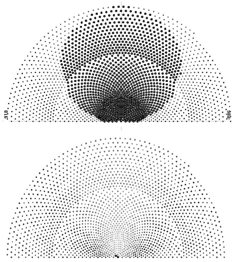
[0047] Figure 1 shows the distribution of heliostats according to the configurations used hitherto: "radial staggered" and "cornfield".

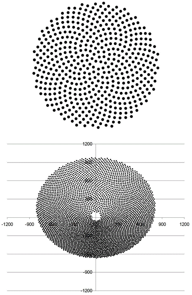
[0048] figure 2 It is shown what the field of heliostats would look like if distributed using the method of the present invention.

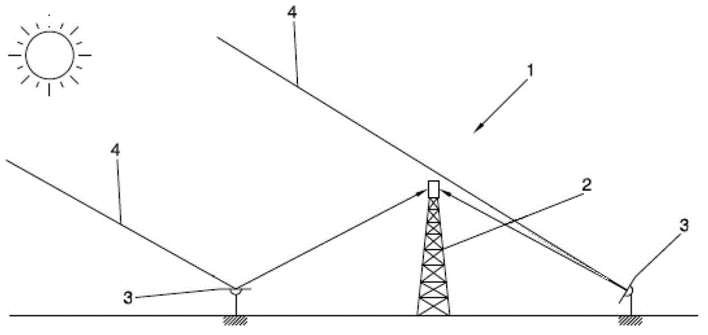
[0049] image 3 Shown is a thermoelectric power plant (1) placed at a particular location of latitude "L", where a receiving tower (2) is erected at a certain height "h", once the sun's rays (4) are directed The heliostat (3) reflection around the receiving tower (2) will reach this height. The electrical energy is generated by the incidence of reflected solar rays (4) on the receiving tower (2), where the sun's rays are focused inside the receiving tower (2), heating a liquid that transmits heat that will be used to drive a turbin...


PUM


Abstract

Method for distributing heliostats in a tower solar plant surrounded by a field of heliostats that reflect the solar radiation to said tower. The distribution method for said heliostats involves imitating the systems found in nature to maximise light capture (plant seeds, leaves or petals) and is described mathematically by Fermat spirals occurring in a Fibonacci number, through the placement, in polar coordinates, of each heliostat according to a radius and an angle defined by Formula (I) where: rn is the distance from the tower (2) to the position of the heliostat (3), ?n is the angle formed by the radius rn and the radius rn-1, n is the number of the heliostat (3) to be placed, Cn is a constant that depends on each placement and corresponds to the compactness index of the heliostats (3) in the plant, i is the irrational limit of the golden section, i.e. (Formula II)

Description

technical field [0001] The invention belongs to the field of generating electrical energy from solar radiation by means of a power station with similar central tower receivers. [0002] The objectives of the invention include: achieving optimum performance of a thermoelectric power plant by selectively distributing the heliostats with respect to the receiving tower. Background technique [0003] A thermoelectric solar power plant is an industrial facility in which the heating of a liquid by solar radiation and its use in a convective thermodynamic cycle generates the electricity necessary to drive an alternator to generate electricity in the same manner as a conventional thermal power station . [0004] Constructively, in order to be able to reach high temperatures above 300°C, it is necessary to focus solar radiation and thus obtain satisfactory performance in thermodynamic cycles, which cannot be obtained at low temperatures. The collection and focusing of the sun's rays...

Claims


Application Information

Patent Timeline
Patent Type & Authority Applications(China)
IPC IPC(8): F24J2/10F24S23/70
CPCY02E10/40F24J2002/1076F24J2002/0084F24J2/10F24J2200/04F24S2020/16F24S2201/00F24S2023/87F24S23/70
Inventor M·克罗·加西亚M·普凡德尔C·格里克R·奥苏纳·冈萨雷斯-阿圭勒
Owner ABENGOA SOLAR NEW TECH SA
Why Eureka
Try Eureka