Marine floating type platform narrow pipe wind-concentrating generating system
What is Al technical title?
Al technical title is built by PatSnap Al team. It summarizes the technical point description of the patent document.
A power generation system and power generation sub-system technology, which is applied in wind power generation, wind power generator components, wind power engines, etc., can solve the problems of lack of autonomy in core technology, no expert literature and patent reports, etc., and achieve long service life and low cost. Low, the effect of solving difficult migration
Active Publication Date: 2014-05-14
JIANGSU ZHONGYUN WIND POWER SCIENCE & TECHNOLOGY CO LTD
View PDF6 Cites 1 Cited by
Summary
Abstract
Description
Claims
Application Information
AI Technical Summary
This helps you quickly interpret patents by identifying the three key elements:
Problems solved by technology
Method used
Benefits of technology
Problems solved by technology
But it can really be popularized and applied, adapting to large-scale deployment, and can produce tens of megawatts, or even hundreds of megawatts of power on a single sea-based platform. , Intensification, into an alternative and novel special-purpose wind turbine for power generation, whether it is professional manufacturing technology, proprietary marine floating platform, full-time technical personnel, proprietary technical equipment, and core technology autonomy are seriously lacking
[0004] After further searching and market research, no expert documents and patent reports completely consistent with or similar to the present invention have been found
Method used
Image
Click on the blue label to locate the original text in one second.
Reading with bidirectional positioning of images and text.
Examples
Embodiment Construction
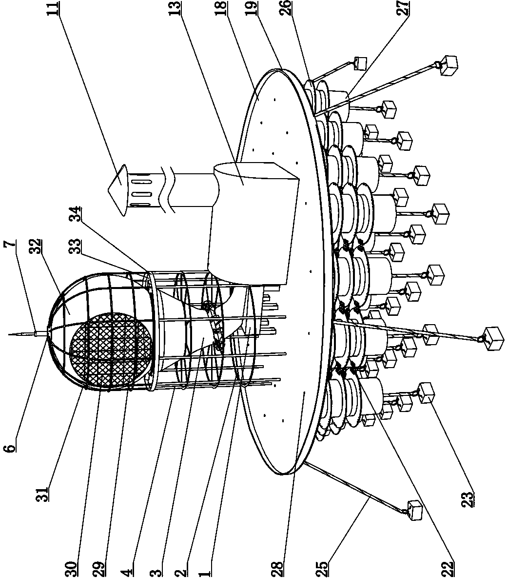
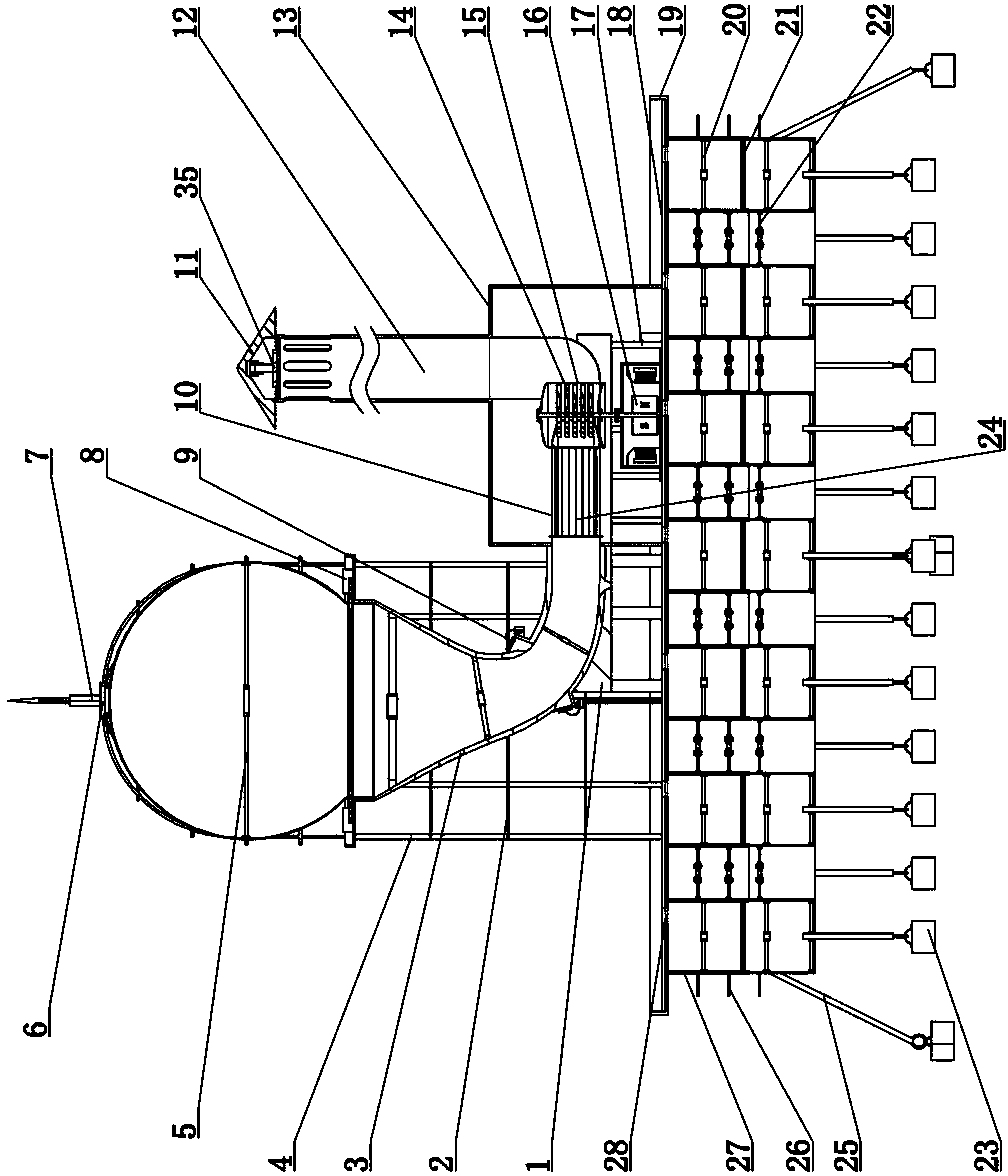
[0028] refer to figure 1 , figure 2 As shown, an ocean floating platform narrow tube wind gathering power generation system of the present invention is realized by the following technical solutions:
[0029] The narrow tube wind gathering power generation system of the marine floating platform of the present invention comprises a narrow tube wind gathering sub-system and a marine carrying platform subsystem.
[0030] The narrow tube wind collecting electronic system is composed of base 1, ring beam 2, narrow tube body 3, main column 4, wheel support 5, intersection fixing seat 6, lightning rod 7, risk avoidance control component 8, suction window Component 9, regular plate 24, regular plate shell 10, top cap 11, air-inducing cylinder 12, mechanical room 13, wind engine 14, wind engine outer shell 15, generator 16, attached column 17, wind gathering inlet 29, The protective net 30, the arc column 31, the spherical body 32, the platform 33, the safety wall B 34, and the hydra...
PUM
Abstract
The invention provides a marine floating type platform narrow pipe wind-concentrating generating system, relates to significant core technologies of comprehensive subjects including main body module modeling, member combination, load bearing and buoyancy force, fluid change, narrow pipe effect, infrastructures, aerodynamics, structural mechanics, turbine effect, electric energy conversion and the like and belongs to the technical field of marine floating type platform wind power generation systems. The marine floating type platform narrow pipe wind-concentrating generating system comprises a narrow pipe wind-concentrating generating subsystem and a marine load-bearing platform subsystem. The narrow pipe wind-concentrating generating subsystem consists of a base platform, a ring beam, a narrow pipe body, a main column, a wheel type support, an intersection fixing seat, a lightning rod, a hedge control assembly, a suction window assembly, an induced air barrel body, a wind power engine, a wind power engine outer casing, a generator, an attached column, a wind-concentrating inlet, a protective screen, a circular arc column, a spherical body, a platform, a hydraulic seal cover and the like. The marine load-bearing platform subsystem consists of a floating platform deck, a safety wall A, a hub support, a partition layer, a connecting piece, a sinking block, an inhaul cable, a flat wave plate, a floating barrel body and a manhole.
Description
technical field [0001] The narrow tube wind gathering power generation system of the marine floating platform of the present invention involves a main module shape, component synthesis, bearing and buoyancy, fluid transition, narrow tube effect, infrastructure, aerodynamics, structural mechanics, turbine effect, and electric energy. It belongs to the technical field of marine floating platform wind power generation system. Background technique [0002] my country is a large ocean country, with a coastline of more than 18,000 kilometers and a marine exclusive economic zone of 3 million square kilometers. This area called "blue land" is about one-third of my country's land area. The extremely rich resources are the main source of material basis for the survival and development of our Chinese nation in the future. As a part of natural ocean resources, wind energy has a powerful advantage of being inexhaustible, and it can especially bring abundant power supply for future develo...
Claims
Application Information
Patent Timeline
Application Date:The date an application was filed.
Publication Date:The date a patent or application was officially published.
First Publication Date:The earliest publication date of a patent with the same application number.
Issue Date:Publication date of the patent grant document.
PCT Entry Date:The Entry date of PCT National Phase.
Estimated Expiry Date:The statutory expiry date of a patent right according to the Patent Law, and it is the longest term of protection that the patent right can achieve without the termination of the patent right due to other reasons(Term extension factor has been taken into account ).
Invalid Date:Actual expiry date is based on effective date or publication date of legal transaction data of invalid patent.
Patent Type & Authority Patents(China)
IPC IPC(8): F03D9/00F03D11/00B63B35/44
CPCY02E10/722Y02E10/727Y02E10/72
Inventor 姚伯龙李勇强杨伟涛谢玉琪张红旭
Owner JIANGSU ZHONGYUN WIND POWER SCIENCE & TECHNOLOGY CO LTD