

MEMS (micro electro mechanical system) triaxial acceleration transducer and manufacture method thereof
A technology of axial acceleration and sensors, which is applied in the field of microelectronic machinery and sensing technology, can solve the problems that the sensitivity characteristics and damping characteristics cannot be taken into account at the same time, the production is complicated, and the sensitivity is low, so as to improve the detection sensitivity and performance stability. The effect of high utilization
- Summary
- Abstract
- Description
- Claims
- Application Information
AI Technical Summary
Problems solved by technology
Method used
Image

Examples
Embodiment 1
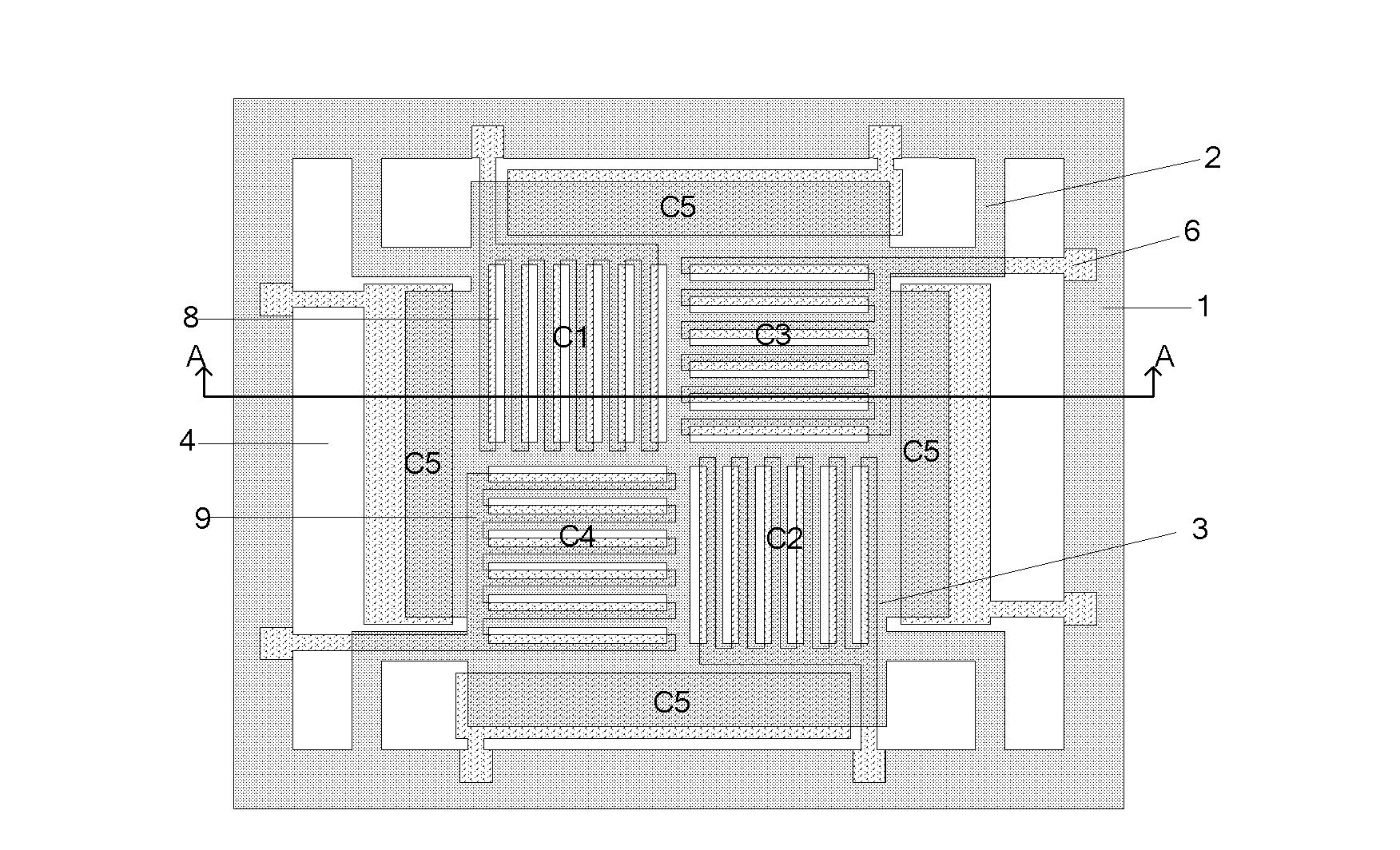
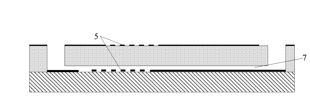
[0041] figure 2 It is a schematic diagram of the MEMS three-axis micro-acceleration sensor structure of the embodiment of the present invention; and image 3 is along figure 2 A schematic cross-sectional view taken along line A-A is shown. figure 2 and image 3 The shown capacitive bulk silicon micromachined three-axis acceleration sensor according to the embodiment of the present invention includes a two-layer structure, which are respectively an upper sensitive element layer and a lower support layer.
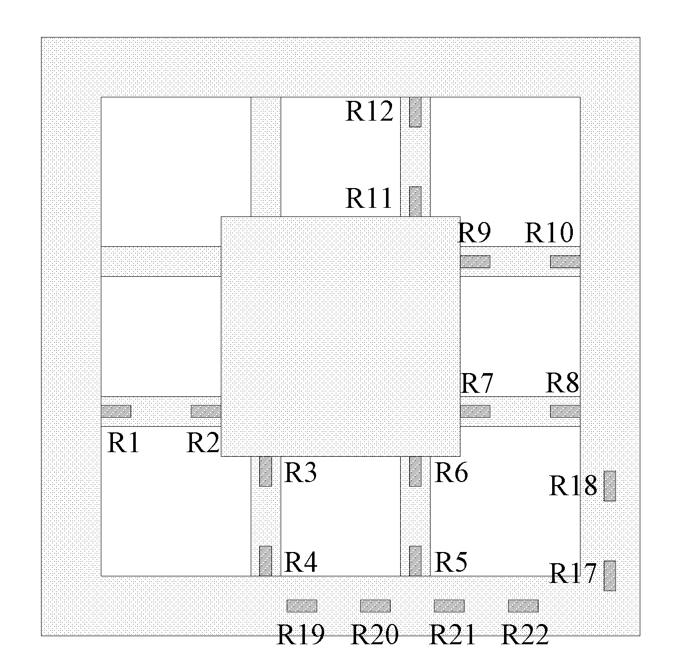
[0042] Specifically, Figure 4 It is a schematic diagram of the layer structure of the sensitive element in the embodiment of the present invention. Figure 5 It is a schematic diagram of the structure of the lower electrode of the grid-type capacitor located on the surface of the lower support according to the embodiment of the present invention.
[0043] As shown in the figure, the sensitive element layer is composed of a supporting frame 1 , an elastic beam 2 , a q...
Embodiment approach
[0055] Reference to the manufacturing method of the capacitive three-axis acceleration sensor involved in Embodiment 1 of the present invention Figure 6 Shown process flow diagram is described, and concrete process implementation method comprises following steps (1) to (10):
[0056] (1) First thin the low-resistance silicon to the required thickness, such as Figure 6 as shown in S1;
[0057] (2) Oxidation, photolithography, and corrosion of the cavity on the back of the mass block (i.e. low-resistance silicon), the depth of the cavity is, for example, 3 μm, such as Figure 6 as shown in S2;
[0058] (3) The material of the lower support is glass, sputtered metal, such as Figure 6 as shown in S3;
[0059] (4) Through photolithography and corrosion to form the lower electrode of the grid capacitor, such as Figure 6 as shown in S4;
[0060] (5) The silicon chip and the lower support are anodically bonded to form a bonded sheet (including both the silicon chip and the l...
Embodiment 2
[0067] Reference to the manufacturing method of the capacitive grid-type MEMS three-axis acceleration sensor involved in this embodiment Figure 7The process flow chart shown is described, and the sensor structure is basically the same as that of Example 1, the main difference is that the materials of the sensitive mass and the lower support body and the manufacturing scheme of the upper electrode of the grid capacitor are different. In this embodiment, the sensitive mass The block is made of high-resistance silicon material, on which the upper electrode 8 of a metal grid capacitor is made, and the thickness of the mass block 3 can be selected according to needs. The specific process implementation method includes the following steps (1) to (8):
[0068] (1) First thin the high-resistance silicon to the required thickness, such as Figure 7 shown in S11;
[0069] (2) Form the cavity on the back of the mass block by photolithography and corrosion, the depth of the cavity is, f...
PUM
 Abstract
Description
Claims
Application Information