Multilayer type power inductor

一种功率电感、间隙层的技术,应用在电感器、固定电感器、电感/变压器/磁铁制造等方向,能够解决电感变化较大、多层型功率电感器厚度增加、功率电感器产生应力等问题

Inactive Publication Date: 2012-10-31
SAMSUNG ELECTRO MECHANICS CO LTD
View PDF6 Cites 2 Cited by
  • Summary
  • Abstract
  • Description
  • Claims
  • Application Information

AI Technical Summary

Problems solved by technology

A multilayer type power inductor has a disadvantage in that the inductance (L) value varies greatly as a current is applied thereto; however, has an advantage in that it has smaller size and thinner thickness, and is also advantageous in terms of DC resistance (see figure 1 )
In other words, multilayer type power inductors have a disadvantage in that the value of inductance (L) varies greatly as current is applied thereto compared to wire wound type power inductors
[0010] However, this multilayer type power inductor has a disadvantage in that the change in inductance value with current applied thereto is large with temperature change, making the temperature stability low
However, when a gap sheet having a thicker thickness is used, the thickness (t direction) of the multilayer type power inductor increases
[0056] (2) A predetermined level of magnetic flux is blocked; however, there is a risk of delamination at the time of sintering due to a difference in contraction percentage between the ZnCu ferrite and the ferrite material of the body and in the power inductor Stresses may develop in the internal part of the
[0057] (3) Bias-TCL characteristics deteriorate due to diffusion of gap layer

Method used


Image

  • Multilayer type power inductor
  • Multilayer type power inductor
  • Multilayer type power inductor

Examples


Embodiment 1

[0105] According to the interstitial layer composition of the present invention by adding TiO based on 100mol% 2 The raw material is 0.001mol% CuO, 0.001mol% ZnO, 0.001mol% Fe 2 o 3 , and 0.001mol% Bi 2 o 3 to prepare.

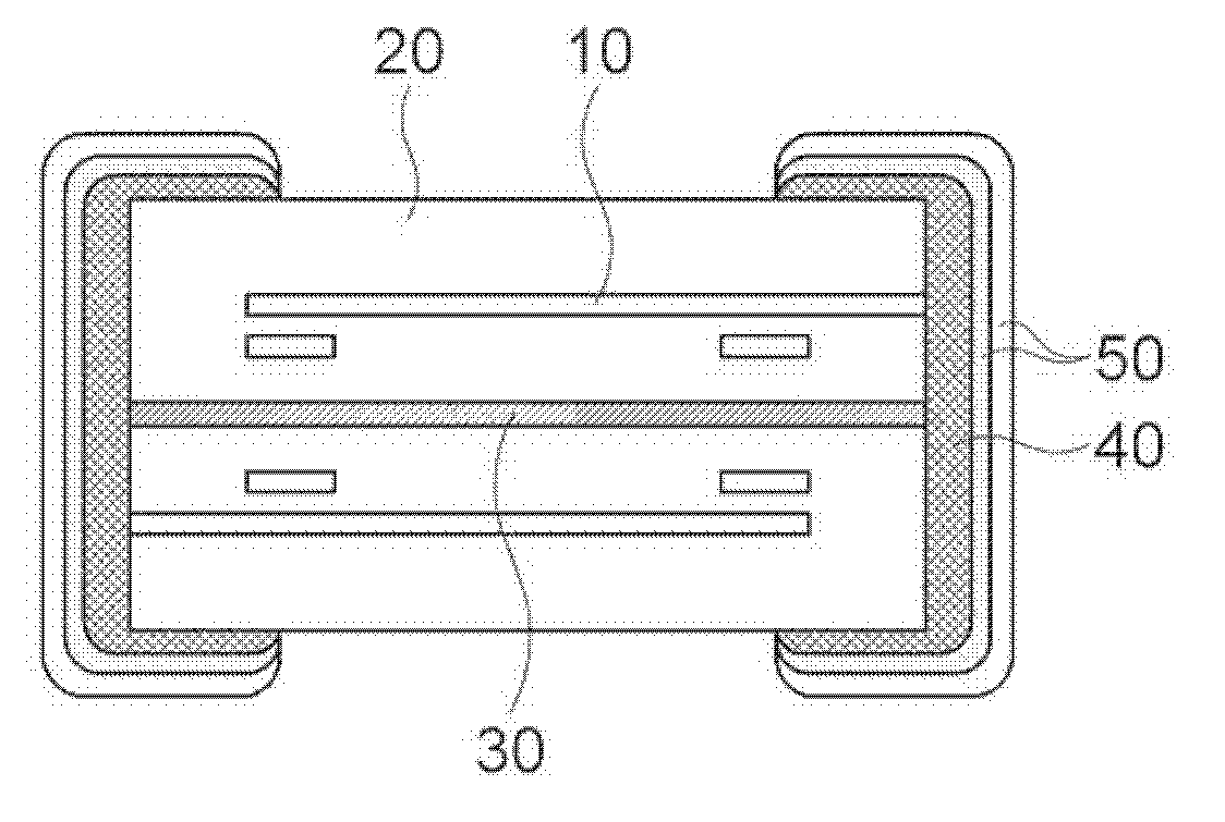
[0106] A gap layer comprising a gap layer composition prepared and having such as Figure 8 The structure shown is a multilayer type power inductor.

[0107] Ag is used as the material of the internal electrodes, and the bulk layer is formed by adding thereto at least one additive selected from Bi within 0.2 mol% based on 100 mol% of NiZnCu ferrite 2 o 3 , CoO and TiO 2 composed of groups.

[0108] The multilayer type power inductor according to the present invention has a structure in which three gap layers (15 μm) are formed between bulk layers.

experiment example 1

[0112] Experimental Example 1: Structure Confirmation

[0113] The structures of the gap layer and the bulk layer of the multilayer type power inductors manufactured according to Example 1 and Comparative Example 1 of the present invention were observed using a scanning electron microscope (SEM). The observed results are shown in Figure 9A to Figure 9C and Figure 10 middle.

[0114] In accordance with Comparative Example 1 in which the existing ZnCu ferrite was used as the material of the gap layer Figure 9A In the case of , the gap layer and the bulk layer are formed separately. However, it was confirmed from actual SEM photographs that the gap layer 30 and the bulk layer 20 were almost indistinguishable from each other.

[0115] However, from Figure 9B It can be confirmed that the interstitial layer 30 formed according to the present invention has a non-porous structure 31 at a portion in contact with the bulk layer 20, and has a porous structure 32 at a portion n...

experiment example 2

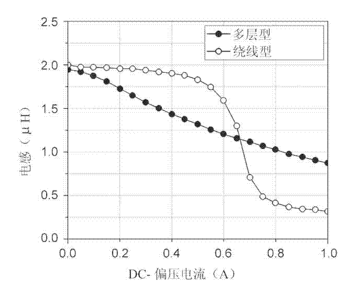
[0117] Experimental Example 2: Confirmation of Bias-TCL Characteristics

[0118] The bias-TCL characteristics of the multilayer power inductors manufactured according to Example 1 and Comparative Example 1 of the present invention were confirmed. Confirmed results are shown in Figure 11 and Figure 12 middle.

[0119] The upper limit of the inductance value of the bias-TCL of each of the multilayer type power inductors manufactured according to Example 1 and Comparative Example 1 of the present invention was about 6 μH, and each of the bias-TCL characteristics was at 0.5 A The following is confirmed based on the inductance value of 2.25μH.

[0120] In the case of the multilayer type power inductor manufactured according to Comparative Example 1, it was confirmed that the bias-TCL characteristics significantly differed with temperature, as Figure 11 shown. That is, it was confirmed that the initial inductance value has a significant difference with temperature. In add...


PUM

PropertyMeasurementUnit
Curie pointaaaaaaaaaa
melting pointaaaaaaaaaa

Abstract

Disclosed herein is a multilayer type power inductor including: a plurality of body layers including internal electrodes and having magnetic material layers stacked therein,and a plurality of gap layers, wherein the gap layer has an asymmetrical structure. In the multilayer type power inductor, portions that are in contact with the body layers have, a non-porous structure, which is a dense structure, and portions that are not in contact with the body layers have a porous structure, such that the gap layer has the asymmetrical structure. Therefore, a magnetic flux propagation path in a coil is dispersed to suppress magnetization at a high current, thereby making it possible to improve a change in inductance (L) value according to the application of current.

Description

[0001] References to related applications [0002] This application claims the benefit of Korean Patent Application Serial No. 10-2011-0038604, filed Apr. 25, 2011, entitled "Multilayer Type Power Inductor," which is hereby incorporated in its entirety as Incorporated by reference in this application. technical field [0003] The present invention relates to a multilayer type power inductor, and more particularly, to a multilayer type power inductor having improved temperature characteristics by including a gap layer having an asymmetric structure. Background technique [0004] Multilayer type power inductors are mainly used in power supply circuits such as DC-DC converters in portable devices. Multilayer type power inductors having small size, high current, low DC resistance, etc. have been mainly developed. In accordance with the trend for DC-DC converters having high frequency and small size, the use of multilayer type power inductors instead of existing wire-wound type...

Claims


Application Information

Patent Timeline
Patent Type & Authority Applications(China)
IPC IPC(8): H01F37/00H01F41/00
CPCH01F17/04H01F17/0013H01F37/00H01F27/292H01F41/00H01F17/00H01F27/30
Inventor 金明基宋昭娟金益燮安成庸韩镇宇孙受焕
Owner SAMSUNG ELECTRO MECHANICS CO LTD
Why Eureka
Try Eureka