Accuracy control method for single-phase diode clamping three level midpoint potential imbalance

A diode clamping and potential unbalanced technology, applied in electrical components, output power conversion devices, AC power input conversion to DC power output, etc., can solve midpoint potential fluctuations in modulation methods and realize complex, diode clamping topologies Solve problems such as midpoint potential fluctuations, achieve the effect of simple method and good reference value

Inactive Publication Date: 2012-10-31
XI AN JIAOTONG UNIV
View PDF2 Cites 21 Cited by
  • Summary
  • Abstract
  • Description
  • Claims
  • Application Information

AI Technical Summary

Problems solved by technology

However, due to the inconsistency of the switching device and the capacitance characteristics of the DC side, the existence of disturbances, and the difference in modulation methods, it may cause fluctuations in the midpoint potential
The diode-clamp topology has an inherent problem with midpoint potential fluctuations and shifts
However, if this idea is applied to a single-phase system, DC interference will be introduced into the phase, and a method must be found to remove this interference
Literature [18-20] found through the precise analysis of the three-phase system that it is the even harmonics that can affect the midpoint potential balance, so by constructing the corresponding load on the load side or injecting the corresponding even harmonics into the modulation wave wave to remove the midpoint imbalance, but it is very complicated to implement

Method used


Image

  • Accuracy control method for single-phase diode clamping three level midpoint potential imbalance
  • Accuracy control method for single-phase diode clamping three level midpoint potential imbalance
  • Accuracy control method for single-phase diode clamping three level midpoint potential imbalance

Examples


Embodiment Construction

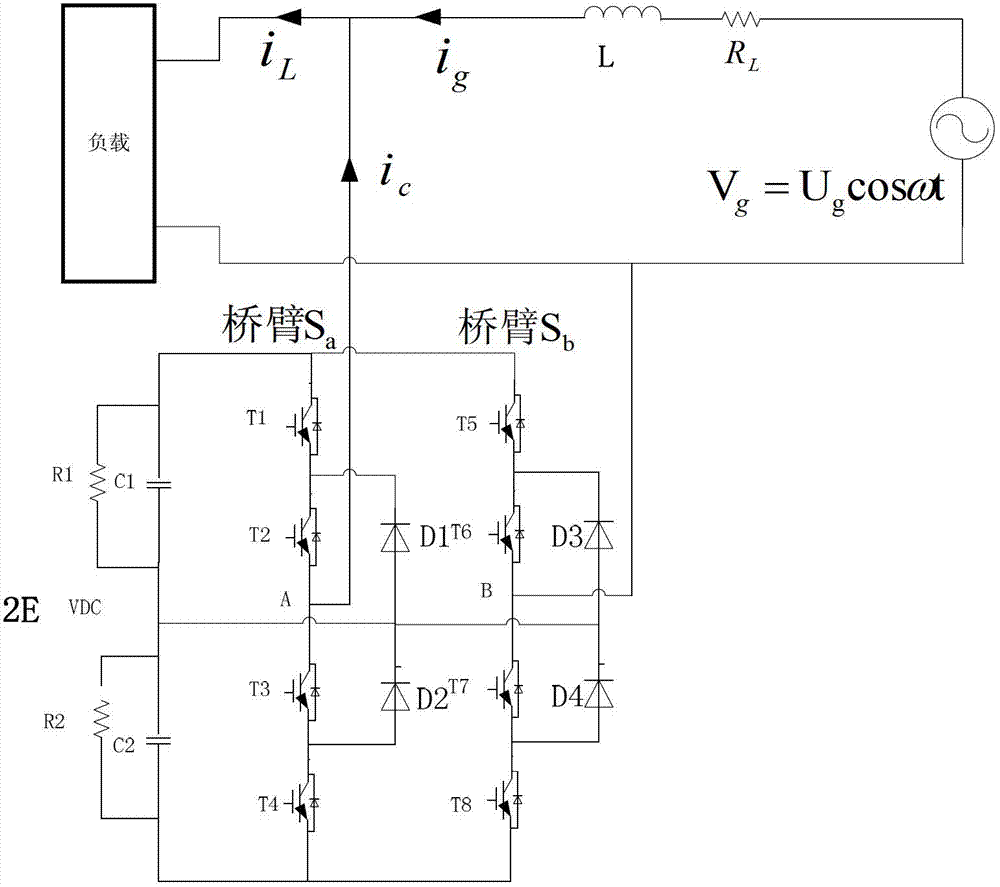
[0067] refer tofigure 1 , a diode clamp topology three-level grid-connected converter is connected between the grid and the load, and the grid-connected converter operates as a reactive power compensator. In order to better verify the control effect of the control method on the midpoint, the Side C 1 A small resistor R is added to the terminal 1 To simulate its large loss, so a large active component will be used in the experimental current. The main circuit structure of the diode-clamped multilevel grid-connected converter mainly includes: a diode-clamp topology module, an incoming line inductance, and a load side. Each diode clamp topology module is composed of two DC side energy storage capacitor elements and a voltage source PWM converter, in which the DC side energy storage element is generally composed of power capacitors connected in series and parallel, and the voltage source PWM converter uses a fully controlled device Such as IGBT, GTO and other components.

[006...


PUM


Abstract

The invention provides an accuracy control method for single-phase diode clamping three level midpoint potential imbalance, which specially aims at the accuracy control of the midpoint potential imbalance by analyzing the influence of the zero level to the direct current-side midpoint potential, and changing the distribution of the zero level among different bridge arms due to the symmetry and the redundancy under the condition that the outlet voltage wave form is not changed and the direct current component is not led, wherein the control method is only relevant to the modulating wave of each module, and is suitable for a large-scale cascade diode clamping topological structure. According to the method, the modulating wave of each module is divided into two parts, the two modulating waves are equal in size and reversed in directions and respectively control the left half bridge and the right half bridge of the diode clamping, and the required direct current component is injected into the modulating wave as required, so that the accuracy control of the midpoint potential can be formed, and additional auxiliary devices are not needed, therefore, the method is simple and easy. The simulation and experiment results show the exactness and the reliability of the method, so that a good reference value can be provided for the engineering application.

Description

technical field [0001] The invention belongs to the field of power electronics, and in particular relates to a single-phase diode clamping three-level midpoint potential unbalance precise control method. Background technique [0002] The idea of ​​multilevel converter was first proposed by Nabae et al. in the early 1980s. Its general structure is to synthesize the step wave by several level steps to approximate the sinusoidal output voltage. Compared with traditional two-level converters, multi-level voltage-type converters can generate M-step output voltages, with more degrees of freedom in output voltages, and are more suitable for matching high voltage levels; one-time dv / dt of switching elements is usually only the traditional double Level 1 / (M-1), the problem of electromagnetic interference (EMI) is greatly reduced; in order to eliminate the same harmonic, the PWM control method adopted by the two levels has high switching frequency and large loss, while the multi-leve...

Claims


Application Information

Patent Timeline
Patent Type & Authority Applications(China)
IPC IPC(8): H02M7/487
Inventor 何英杰林继亮杜思行刘进军
Owner XI AN JIAOTONG UNIV
Why Eureka
Try Eureka