Sewage treatment system and application thereof

A sewage treatment system and sewage treatment technology, applied in water/sewage multi-stage treatment, biological water/sewage treatment, water/sludge/sewage treatment, etc., can solve the problems of high ammonia nitrogen concentration, low nitrification efficiency, and nitrification low bacterial activity

Inactive Publication Date: 2012-11-07
SHANGHAI UNIVERSITY OF ELECTRIC POWER
View PDF3 Cites 11 Cited by
  • Summary
  • Abstract
  • Description
  • Claims
  • Application Information

AI Technical Summary

Problems solved by technology

[0007] The purpose of the present invention is to provide a new type of sewage treatment system and use it to solve the above-mentioned technical problems such as low activity of nitrifying bacteria, low nitrification efficiency, and high concentration of ammonia nitrogen in winter low-temperature effluent in urban sewage treatment plants that accept long-distance pipelines to transport sewage. Methods of Sewage Treatment

Method used


Image

  • Sewage treatment system and application thereof
  • Sewage treatment system and application thereof

Examples


Embodiment 1

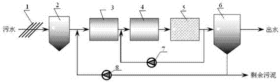
[0022] Typical traditional sewage nitrogen and phosphorus removal treatment system, the schematic diagram of the treatment process is as follows figure 1 As shown, it includes sewage treatment grid 1, grit chamber 2, anaerobic tank 3, anoxic tank 4, aerobic tank 5, and secondary sedimentation tank 6. After being treated by grid 1, the sewage enters grit chamber 2, and the grit chamber The mixed solution obtained after the effluent from the pool 2 is treated by the biological treatment unit composed of the anaerobic pool 3, the anoxic pool 4, and the aerobic pool 5 enters the secondary sedimentation pool 6;

[0023] The secondary settling tank 6 is provided with two outlets, one is the discharge outlet of the treated sewage, and the other is the discharge outlet of the excess sludge, and the discharge outlet of the excess sludge is provided with a bypass after the sludge return pump 8 will be used The remaining sludge discharged from the secondary settling tank 6 is returned t...

Embodiment 2

[0031] Utilize the typical traditional sewage denitrification and dephosphorization treatment system described in Example 1 and the sewage treatment system of the present invention to respectively treat the sewage of Shanghai Bailonggang sewage treatment plant whose water intake is long-distance pipeline transport sewage, and treat The amount of sewage is 200L / d, the COD of sewage influent is 318.6 mg / L, the ammonia nitrogen is 29.75 mg / L, and the sulfide content is 13.1 mg / L.

[0032]During the winter low-temperature operation stage (January to February), the effluent ammonia nitrogen of the sewage treatment system of the present invention is 4.70±1.91 mg / L, while the effluent ammonia nitrogen of a typical traditional sewage denitrification and phosphorus removal system is 17.76±4.74 mg / L L;

[0033] In the period of normal temperature operation (4~6 months), the final ammonia nitrogen in the effluent of the sewage treatment system of the present invention is 1.23±1.12 mg / ...


PUM


Abstract

The invention discloses a sewage treatment system which comprises a grating, a grit tank, a preaeration tank, an anaerobic tank, an anoxia tank, an aerobic tank and a secondary sedimentation tank. Sewage enters the grit tank after being treated by the grating, water discharged from the grit tank sequentially enters a biological treatment unit composed of the anaerobic tank, the anoxia tank and the aerobic tank to be treated, obtained mixed liquid enters the secondary sedimentation tank, two outlets are arranged on the secondary sedimentation tank, one outlet is a discharging port of treated sewage, and the other outlet is a discharging port of surplus sludge. A bypass is arranged on the discharging port of the surplus sludge, and one part of the surplus sludge discharged from the secondary sedimentation tank flows back to the preaeration tank through a sewage backflow pump. Simultaneously, one part of the mixed liquid from the aerobic tank flows back to the anoxia tank through a mixed liquid backflow pump on the bypass. The sewage treatment system has the advantages of being high in nitrobacterium activity, high in nitrification rate, high in ammonia nitrogen removing rate and the like.

Description

technical field [0001] The invention relates to a sewage treatment system and its application in sewage treatment, and belongs to the technical field of environmental protection and rational utilization of water resources. Background technique [0002] Water pollution and water shortage are one of the serious environmental problems facing our country. In 2011, the national wastewater discharge was 65.21 billion tons, of which the chemical oxygen demand discharge was 24.999 million tons and the ammonia nitrogen discharge was 2.604 million tons. A large amount of wastewater discharge has caused serious pollution of surface water bodies in my country, seriously threatening the ecological environment, industrial and agricultural production, and human safety and health. In recent years, in order to control water pollution and protect water resources, relevant state departments have introduced a series of water pollutant control policies such as total pollutant discharge reductio...

Claims


Application Information

Patent Timeline
Patent Type & Authority Applications(China)
IPC IPC(8): C02F9/14C02F3/30C02F3/12
CPCY02W10/10
Inventor 周振邢灿王罗春
Owner SHANGHAI UNIVERSITY OF ELECTRIC POWER
Why Eureka
Try Eureka