Method for controlling twist redistribution

A re-distribution and bearding technology, applied in textiles and papermaking, drafting equipment, spinning machines, etc., can solve the problems of inconvenient system installation, unfavorable large drafting, complex structure of the rear area, etc., to achieve increased compactness, Prevent twist redistribution and maintain uniform drafting effect

Inactive Publication Date: 2012-11-07
JIANGNAN UNIV
View PDF4 Cites 3 Cited by
  • Summary
  • Abstract
  • Description
  • Claims
  • Application Information

AI Technical Summary

Problems solved by technology

The above method mainly adopts the apron structure in the rear area to improve the control force on the fiber and then improves the drafting ability of the rear area to a certain extent, but this method makes the structure of the rear area more complicated on the one hand, which is not convenient for the actual system installation; on the other hand On the one hand, adding an apron structure in the back area increases the control force on the fibers, but the speed change points are only concentrated near the periphery of the apron, which is not conducive to the large draft of the roving itself with a certain twist, and it is easy to cause draft. Uneven stretching seriously affects the yarn quality

Method used


Image

  • Method for controlling twist redistribution
  • Method for controlling twist redistribution
  • Method for controlling twist redistribution

Examples


Embodiment 1

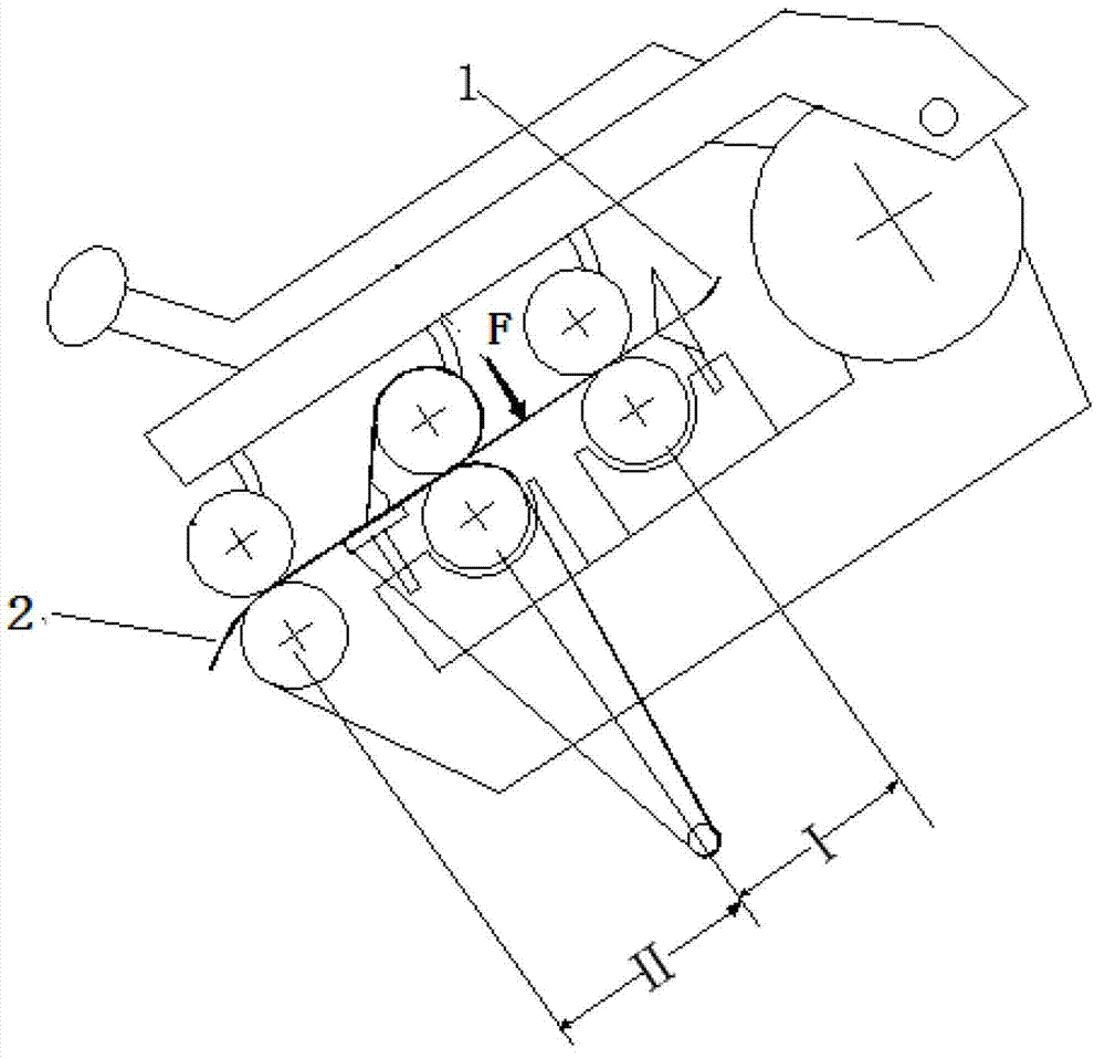
[0024] Taking pure cotton combed 14.6tex yarn spun by EJM128K spinning frame as an example, the roving strand 1 with a basis weight of 4.83g / ·10m and a twist coefficient of 144 is fed from the bell mouth, and the twist coefficient of the spun yarn is set at 380. The stretch ratio is set to 1.88, the total draft ratio is set to 33.03, no pressure is applied, and after the drafting effect of the rear draft zone I and the front draft zone II, it is twisted into a spun yarn 3, and the yarn quality is as shown in Table 1. Show.

Embodiment 2

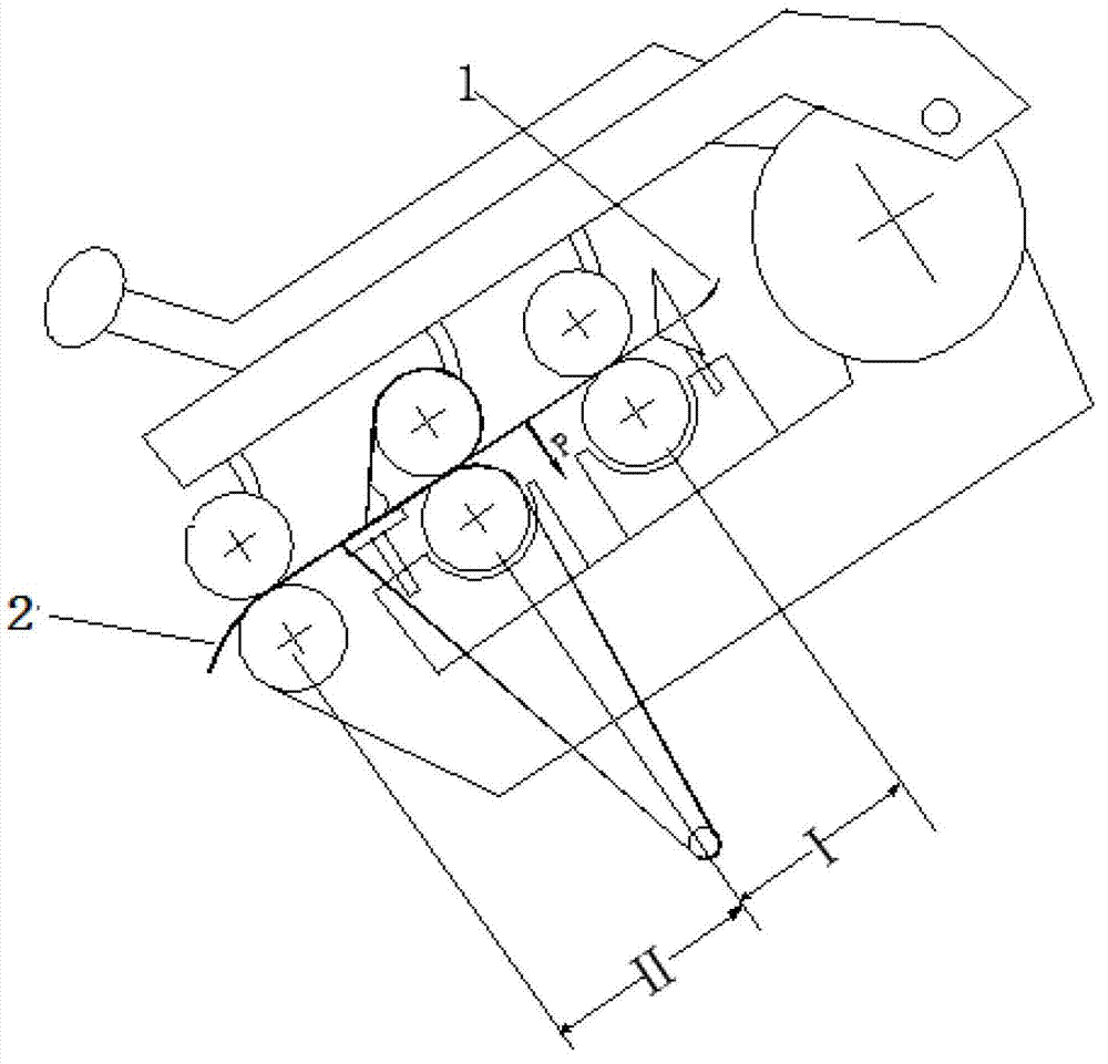
[0026] Taking pure cotton combed 14.6tex yarn spun by EJM128K spinning frame as an example, the roving sliver 1 with a basis weight of 4.83g / ·10m and a twist coefficient of 144 is fed from the bell mouth, and the twist coefficient of the spun yarn is set at 380, and is pulled In stretch zone II, the positioning guide wheel driven by rolling bearings installed on the cradle exerts a positive pressure downward, the pressure is 10N / spindle, the draft ratio of the rear zone is set to 1.88, and the total draft ratio is set to 33.03. After the drafting in the rear drafting zone I and the front drafting zone II, the spun yarn 3 is twisted, and the yarn quality is shown in Table 1.

Embodiment 3

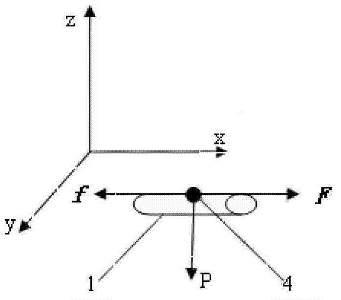
[0028] Still using the EJM128K spinning frame to spin pure cotton combed 14.6tex yarn, the roving sliver 1 with a basis weight of 4.83g / 10m and a twist coefficient of 144 is fed from the bell mouth, and the twist coefficient of the spun yarn is set at 380. The perforated upper apron is used on the roller to cooperate with the upper pin with a hollow structure, and the bottom plane of the lower pin contains air outlet holes, and the corresponding lower pin is added to the rear end of the middle roller to form the jaw in the rear area. The upper part of the hollow lower pin contains negative pressure suction Channel, the negative pressure airflow applied is 3000Pa, the negative pressure airflow acts on the whiskers at the jaws through the air outlet hole of the hollow lower pin and the hole on the perforated upper apron, and then generates reverse pressure on the whiskers passing through the force application point 4 P , the reverse pressure P Frictional resistance to moving whi...


PUM


Abstract

The invention discloses a method for controlling twist redistribution. According to the invention, a back zone force application method is adiopted to apply external force on a strip located in a drawing back zone, a force application point is located on the strip surface of the drawing back zone, component force is produced by the applied external force in a vertical direction of the strip surface of the drawing back zone, a stable frictional force zone is provided for the position of the force application point, the strip is not easy to turn over, simultaneously, compactness of the strip can be effectively improved, twist redistribution can be effectively avoided, and resultant yarn levelness is improved.

Description

technical field [0001] The invention belongs to the technical field of ring spinning, and relates to a method for controlling twist redistribution, in particular to a method for controlling twist redistribution when a large draft multiple is adopted in the rear draft zone of a ring spinning frame. Background technique [0002] Ring spinning technology is the most widely used spinning technology at home and abroad. The drafting system is one of the most important parts of the spinning frame. It draws the fed coarse sand or sliver evenly into a A certain number of finished spun yarns, so the running stability and drafting uniformity of the system involved in the ring spinning frame will directly affect the yarn quality and output of the spun yarn. The improvement of the drafting mechanism of the traditional spinning frame is also one of the most popular research directions in the spinning field. [0003] At present, general-purpose spinning frames all adopt a three-roller dou...

Claims


Application Information

Patent Timeline
Patent Type & Authority Applications(China)
IPC IPC(8): D01H5/18D01H5/72D01H13/10
Inventor 高卫东谢春萍徐伯俊苏旭中刘新金
Owner JIANGNAN UNIV
Why Eureka
Try Eureka