
Smoke waste heat utilizing system at tail of power station boiler applicable to operation in variable working condition

A flue gas waste heat and variable working condition technology, which is applied in the direction of steam boilers, process efficiency improvement, furnaces, etc., can solve the problems of aggravated pipe wall corrosion, ash deposition corrosion, low temperature pipe wall corrosion, etc., to reduce pitting corrosion, Improve the effect of circumvention and reduce the effect of rotation dead zone

Active Publication Date: 2015-07-15
NORTH CHINA ELECTRIC POWER UNIV (BAODING)
View PDF5 Cites 0 Cited by
  • Summary
  • Abstract
  • Description
  • Claims
  • Application Information

AI Technical Summary

Problems solved by technology

[0005] Reducing the exhaust gas temperature of the boiler through waste heat recovery and utilization can improve boiler efficiency and power plant economy, but because the low-temperature flue gas at the tail of the boiler often contains such as SO 2 , SO 3 , NO x When the temperature of the wall surface drops below the acid dew point, the low-temperature pipe wall is prone to strong low-temperature flue gas corrosion, and at the same time forms a cement-like substance mainly composed of calcium sulfate with the fly ash in the flue gas, which makes the flue gas side ventilated The resistance increases, the power consumption of the fan increases, and the corrosion of the tube wall is aggravated, which seriously affects the safe and economical operation of the boiler
At present, there are still relatively few heat exchangers suitable for the utilization of low-temperature flue gas waste heat at the tail of the boiler, and most of them are integral light-tube heat exchangers. The heat exchangers are large and have serious problems of dust accumulation and corrosion.

Method used


Image

  • Smoke waste heat utilizing system at tail of power station boiler applicable to operation in variable working condition
  • Smoke waste heat utilizing system at tail of power station boiler applicable to operation in variable working condition

Examples


Embodiment Construction

[0015] The invention provides a waste heat utilization system of flue gas at the tail of a power plant boiler adapted to variable working conditions. The following will be described in conjunction with the accompanying drawings and embodiments.

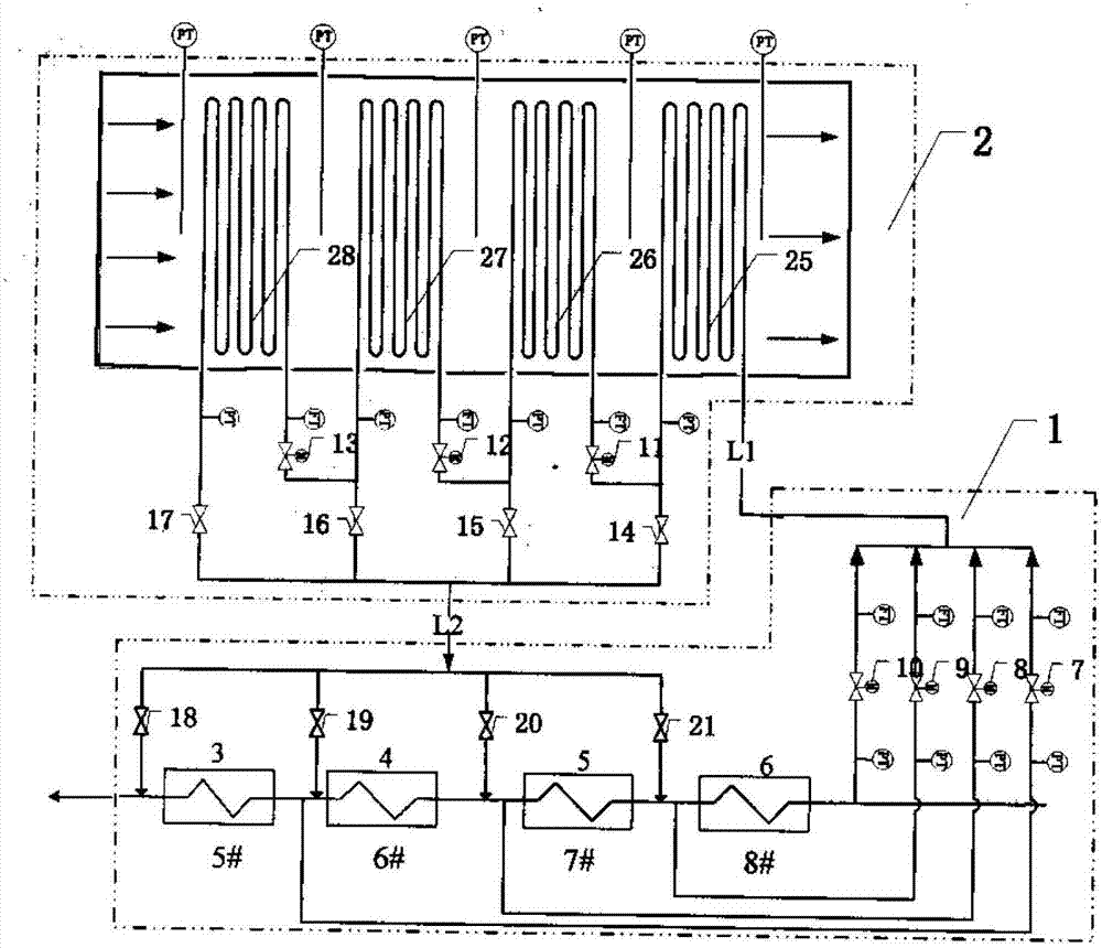
[0016] Such as figure 1 Shown is the specific piping and valve control schematic diagram of the flue gas waste heat utilization optimization integrated system. The system is mainly composed of the heat recovery side subsystem 1 and the staged heat exchange subsystem 2 distributed in the tail flue. Among them, the heat recovery side subsystem 1 is composed of 5# low-pressure heater 3, 6# low-pressure heater 4, 7# low-pressure heater 5 and 8# low-pressure heater 6 in series; it is connected at the entrance of 5# low-pressure heater 3 The 7th valve is connected to the 8th valve at the entrance of 6# low pressure heater 4, the 9th valve is connected to the entrance of 7# low pressure heater 5 and the 10th valve is connected to the entra...


PUM


Abstract

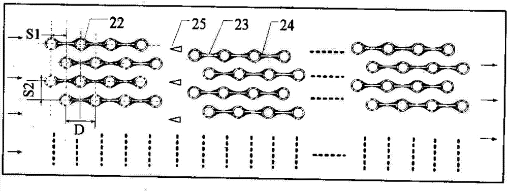
The invention belongs to the technical field of energy saving of waste heat utilization, and particularly relates to a smoke waste heat utilizing system at the tail of a power station boiler applicable to operation in a variable working condition. The smoke waste heat utilizing system mainly consists of a back-heating side subsystem and a step type heat exchange subsystem distributed on a tail flue. A certain amount of condensation water is extracted from an inlet of a certain level heater in the back-heating side subsystem according to a boiler operation working condition, and flows into an inlet of the step type heat exchange subsystem by passing through an L1 pipeline through an outlet of the back-heating side subsystem; after carrying out heat exchange with boiler smoke through each level of heat exchanger pipe group arranged in the step type heat exchange subsystem, an outlet of the step type heat exchange subsystem is connected with an outlet of the certain level heater in the back-heating side subsystem through an L2 pipeline, so that system temperature and flow can be sensitively adjusted, and the system is enabled to be at an optimal operation working condition. Meanwhile, the heat exchange subsystem uses a step type improved film design; pipes of each level of a heat exchanger can be arranged in a double-staggered manner; and a flow guide plate is additionally arranged, so that the airflow resistance is reduced, and the heat conduction efficiency is improved.

Description

technical field [0001] The invention belongs to the energy saving technical field of waste heat utilization, and in particular relates to a boiler tail flue gas waste heat utilization system adapted to the variable working conditions of a power plant. [0002] In view of the change of exhaust gas temperature at the tail of the boiler when the power plant unit is operating under variable conditions, through the hierarchical control of the heat exchanger tube group and the optional design of the input and output of condensate water, the waste heat of the tail flue gas can replace part of the steam extraction to heat the condensate water. Flexible use. At the same time, according to the actual situation of the flue gas at the boiler tail and its circulation flue, the form design of the heat exchanger is improved, so as to ensure the economical and safe operation of the heat exchanger equipment under this working condition. Background technique [0003] Energy conservation and ...

Claims


Application Information

Patent Timeline
Patent Type & Authority Patents(China)
IPC IPC(8): F27D17/00F22D1/02F22B31/08
CPCY02P10/25
Inventor 徐钢杨勇平黄圣伟刘超许诚刘欢刘文毅
Owner NORTH CHINA ELECTRIC POWER UNIV (BAODING)
Learn More