Automatic feeding mechanism for furnace

A technology for automatic feeding and furnace use, which is applied in the direction of furnaces, furnace components, lighting and heating equipment, etc. It can solve problems such as deviation, affect the furnace effect, and unseen problems, and achieve the effect of energy saving

Inactive Publication Date: 2014-05-07
SUZHOU HUIKE EQUIP CO LTD
View PDF6 Cites 0 Cited by
  • Summary
  • Abstract
  • Description
  • Claims
  • Application Information

AI Technical Summary

Problems solved by technology

[0004] However, the feeding mechanism of the above-mentioned structure has the following confusion or technical problems in actual use: First, the plurality of workpieces that were basically in the state of alignment before Deviations often occur during the process of moving towards the entrance of the furnace. Therefore, when one or more of the workpieces deviates, it will interfere with other workpieces, causing piles, affecting the effect of entering the furnace, or even failing to enter the furnace. The current disposal The method is to manually straighten it by the online workers, so the labor intensity of the workers is relatively high, especially for heavy workpieces, it is often difficult to use human physical strength to straighten it; The ground is in the state of going hand in hand into the furnace, which will seriously affect the quality of heat treatment. The specific performance is that the workpieces that enter the furnace first can obtain the heat treatment time required by the process, and the workpieces that enter the furnace after that do not obtain the heat treatment time required by the process. products or even scrapped, because the heat treatment time obtained by the latter is shorter than that of the former; thirdly, it is not enough to maximize energy saving and heat treatment efficiency, because when one or more of the multiple workpieces is obviously lagging behind other workpieces into the furnace In order to ensure that the workpiece entering the furnace obtains the required heat treatment time, the heat treatment time or the heat treatment process can only be extended
[0005] In view of the drawbacks of the above-mentioned prior art, the applicant has searched the literature, but none of the disclosed patents and non-patent literature can solve the above-mentioned problems. Enlightenment of technical problems, for this reason, the applicant has carried out active and persistent exploration and attempt, finally formed the technical scheme that will introduce below

Method used


Image

  • Automatic feeding mechanism for furnace
  • Automatic feeding mechanism for furnace

Examples


Embodiment Construction

[0020] In order to enable the examiners of the patent office, especially the public, to understand the technical essence and beneficial effects of the present invention more clearly, the applicant will describe in detail the following in the form of examples, but none of the descriptions to the examples is an explanation of the solutions of the present invention. Any equivalent transformation made according to the concept of the present invention which is merely formal but not substantive shall be regarded as the scope of the technical solution of the present invention.

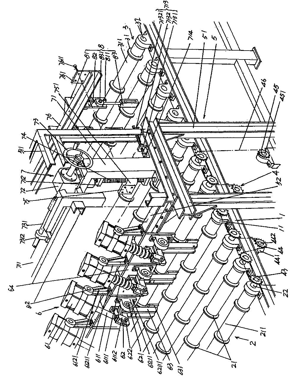
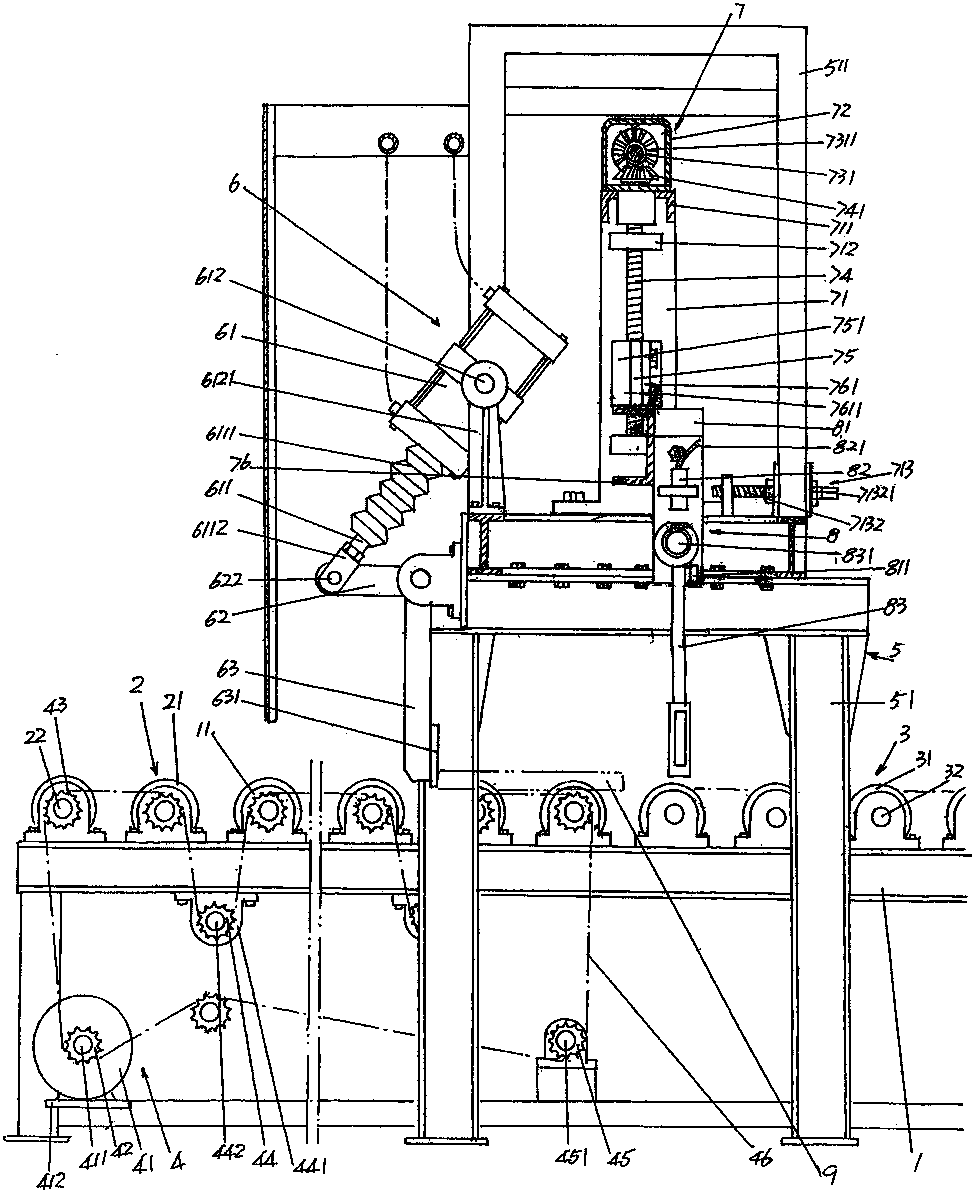
[0021] Please see figure 1 with figure 2 , a feed roller housing 1 with a frame structure is given. On the upper part (also called the top) on both sides of the length direction of the feed roller housing 1 and at positions corresponding to each other, a group of roller bearing seats are fixed at intervals. 11.

[0022] currently by figure 1 Take the position shown as an example (the same below),...


PUM


Abstract

The invention discloses an automatic feeding mechanism for a furnace and belongs to the field of furnace facilities. The automatic feeding mechanism comprises a feeding roller rack, a feeding roller, a transition roller and a feeding roller driving device and also comprises an overhead frame, a workpiece channel opening / closing device, a workpiece signal acquisition unit adjusting device and a workpiece signal acquisition device, wherein the overhead frame comprises a pair of portal frames and a crossbeam; a workpiece channel opening / closing device is arranged along the length direction of the crossbeam; the workpiece signal acquisition unit adjusting device is fixed on the top of the pair of portal frames; the workpiece signal acquisition device is arranged on the workpiece signal acquisition unit adjusting device; a feeding roller workpiece isolating flange ring is arranged in the length direction of the feeding roller; a transition roller workpiece isolating flange ring is arranged in the length direction of the transition roller; a workpiece signal acquisition device is correspondingly arranged above a workpiece lead-in channel; and the transition roller is in transmission connection with the transition roller driving device. The working efficiency is guaranteed, the quality is ensured, the energy is saved, and the labor intensity is lightened.

Description

technical field [0001] The invention belongs to the technical field of furnace facilities, and specifically relates to an automatic feeding mechanism for a furnace, which is matched with heat treatment furnaces such as annealing furnaces and tempering furnaces, so that a plurality of workpieces to be heat treated enter the furnace in a parallel state. Background technique [0002] As known in the industry, during the processing of mechanical parts (such as chain rail plates) and metal materials (such as bars, pipes and forgings, etc.), heat treatment is usually required to ensure quality such as improving hardness. In addition, in order to improve work efficiency and reduce the work intensity of the operator, an automatic feeding mechanism is usually arranged at the entrance of the heat treatment furnace or similar furnace body, and the workpiece is sent into the furnace by the automatic feeding mechanism. [0003] The known structure of the above-mentioned feeding mechanism...

Claims


Application Information

Patent Timeline
Patent Type & Authority Patents(China)
IPC IPC(8): F27D3/00C21D1/00
Inventor 包瑜刘远
Owner SUZHOU HUIKE EQUIP CO LTD
Why Eureka
Try Eureka