Circumferentially distributed burner of natural gas channels

A natural gas, distributed technology, applied in the direction of gas fuel burners, burners, combustion methods, etc., can solve the problems of insufficient mixing of natural gas fuel, incomplete natural gas, etc., to improve the effective utilization rate, increase the contact area, cooling good condition

Inactive Publication Date: 2012-11-14
MAANSHAN TIANZHOU ENERGY SAVING ENG TECH
View PDF10 Cites 2 Cited by
  • Summary
  • Abstract
  • Description
  • Claims
  • Application Information

AI Technical Summary

Problems solved by technology

[0007] The purpose of the present invention is to overcome the deficiency that the natural gas fuel cannot be fully mixed during the combustion process in the prior art, and provide a circumferentially distributed burner for the natural gas channel. The content of CO plays the role of saving energy and reducing consumption

Method used


Image

  • Circumferentially distributed burner of natural gas channels
  • Circumferentially distributed burner of natural gas channels
  • Circumferentially distributed burner of natural gas channels

Examples


Embodiment 1

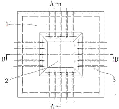
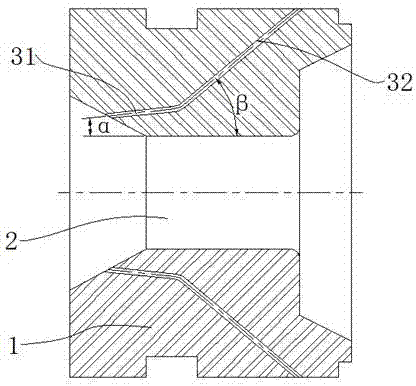
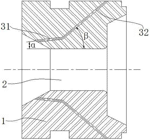
[0031] combine figure 1 , figure 2 and image 3 , a natural gas channel circumferentially distributed burner in this embodiment is mainly composed of a burner brick body 1, a combustion air channel 2 and a natural gas channel 3, and the natural gas channel 3 includes two parts: the nozzle section 31 and the insertion section 32.

[0032] The combustion-supporting air channel 2 in this embodiment is a quadrangular hollow structure and is arranged horizontally, and is located inside the burner brick body 1 . As an outstanding improvement of the present invention, the natural gas passages 3 of the burner are evenly distributed on the four sides of the quadrilateral combustion air passage 2, which plays a role in finely splitting the natural gas fuel. It is worth noting that the natural gas passages in the present invention 3 can adopt other shape structures such as circles in the prior art. As long as there are two or more natural gas channels 3 distributed along the outer pe...

Embodiment 2

[0035] The basic structure of this embodiment is the same as that of Embodiment 1, except that the natural gas passages 3 of the burner are only distributed on two opposite sides of the quadrilateral combustion air passage 2 periphery, and the distance between two adjacent combustion air passages 2 on the same side is 60 mm, the diameter of the natural gas channel 3 is Φ20 mm; the angle α between the nozzle section 31 at the front end of the natural gas channel 3 and the central axis of the combustion air channel 2 is 20°, and the angle α between the insertion section 32 and the central axis of the combustion air channel 2 The angle β is 30°.

Embodiment 3

[0037] The basic structure of this embodiment is the same as that of Embodiment 1, except that the natural gas passages 3 of the burner are only distributed on three sides of the quadrilateral combustion air passage 2 periphery, and the distance between two adjacent combustion air passages 2 on the same side is 40 mm, the diameter of the natural gas channel 3 is Φ5 mm; the angle α between the nozzle section 31 at the front end of the natural gas channel 3 and the central axis of the combustion air channel 2 is 3°, and the angle α between the insertion section 32 and the central axis of the combustion air channel 2 β is 60°.

[0038] After the burners in Examples 2 and 3 are applied to natural gas regenerative forging furnaces, the energy-saving effect is obvious, the emission of CO in the flue gas is reduced by about 8%, and the coal consumption per ton of steel is about 75Kg standard coal / t steel.


PUM


Abstract

The invention discloses a circumferentially distributed burner of natural gas channels and belongs to the technical field of non-premixed gas combustor. The circumferentially distributed burner comprises a burner block body, an oxidizing air channel and the natural gas channels, wherein the oxidizing air channel is a tubular structure inside the burner block body, and two or more natural gas channels are circumferentially distributed around the oxidizing air channel and embedded in the burner block body. A central axial included angle alpha is formed between a burner section at the front end of each natural gas channel and the oxidizing air channel, the alpha is not smaller than zero degree and not larger than ninety degrees, and the burner sections are distributed in the same direction with the oxidizing air channel and join with the oxidizing air channel at the front end of the burner. The circumferentially distributed burner of the natural gas channels can thin and split the natural gas, enlarge contact area of the natural gas and oxidizing air, reduce incomplete combustion amount of the natural gas, and reduce CO (carbon monoxide) content in discharge smoke. Compared with a conventional natural-gas heat accumulating type burner, the circumferentially distributed burner can save energy by 8-10% and has remarkable energy conservation effect, and the service life of the burner is greatly prolonged.

Description

technical field [0001] The invention belongs to the technical field of non-premixed gas burners, and more specifically relates to a circumferentially distributed burner for a natural gas channel, which is especially suitable for a regenerative burner system. Background technique [0002] The regenerative high-temperature air combustion technology called HTAC (High Temperature Air Combustion) abroad is a new concept of combustion technology proposed by foreign countries in the last century. This technology combines recovery of flue gas waste heat with high-efficiency combustion and reduction of NO x With the organic combination of other technologies, it preheats the combustion-supporting air from room temperature to a high temperature of 800~1000°C through high-efficiency heat storage materials, thereby achieving extreme energy saving and extreme reduction of NO x Emissions serve a dual purpose. [0003] Although regenerative high-temperature combustion technology is an ene...

Claims


Application Information

Patent Timeline
Patent Type & Authority Applications(China)
IPC IPC(8): F23D14/58F23D14/66
CPCY02E20/34
Inventor 张西和陈光
Owner MAANSHAN TIANZHOU ENERGY SAVING ENG TECH
Why Eureka
Try Eureka