System and method for controlling online type photovoltaic power generation microgrid without storage device

A technology of photovoltaic power generation system and energy storage device, which is applied to AC networks of the same frequency with different sources, etc., can solve the problems of limited battery life, inseparable from energy storage devices, and high cost, improve conversion efficiency, and benefit a wide range of The effect of promotion and cost reduction

Inactive Publication Date: 2012-11-14
SHANGHAI JIAO TONG UNIV
6 Cites 31 Cited by

AI-Extracted Technical Summary

Problems solved by technology

[0005] After searching the public literature of the existing technology, it was found that the Chinese patent publication number: CN101697421A, (public date 2010.04.21,) discloses a micro-grid photovoltaic micro-power control system, and consults the current research on micro-grid at home and abroad In most cases, all designs are inseparable from energy storage devices (usually batteries). Considering the limited life...

Method used

As Fig. 6 is DC/AC converter 4 full-bridge inverter circuit structural block diagrams, grid-connected inverter adopts current control, and compensation network is PI adjustment, and current loop adopts current hysteresis instantaneous control technology, promptly takes inductor current as The amount of feedback has a strong ability to resist short-circuit loads, and the quality of the output voltage waveform is high whe...

Abstract

The invention discloses a system and a method for controlling an online type photovoltaic power generation microgrid without a storage device. The system comprises a photovoltaic component, a power controller, a grid-connected inverter system, a current detection device and a reverse-power protector, the photovoltaic component is connected with the grid-connected inverter system through the power controller, output of the grid-connected inverter system and grid current are connected to simultaneously supply power to load, the power controller enables a photovoltaic power generation system to be in a variable power output state and dynamically adjusts output power of the photovoltaic power generation system according to changes of the load, the current detection device detects magnitude and phase position of the grid current as current feedback control signals of the grid-connected inverter system, and the reverse-power protector is positioned between the microgrid and an outer grid to stop the microgrid from transmitting current to the outer grid. The system is free of a storage battery energy storage system, the outer grid is only a supplement when the microgrid is in power shortage, and power transmission to the outer grid is effectively avoided, so that effects of electricity saving can be realized without upgrading power transmission networks and power distribution networks, and popularization is facilitated.

Application Domain

Technology Topic

Image

  • System and method for controlling online type photovoltaic power generation microgrid without storage device
  • System and method for controlling online type photovoltaic power generation microgrid without storage device
  • System and method for controlling online type photovoltaic power generation microgrid without storage device

Examples

  • Experimental program(1)

Example Embodiment

[0029] The technical solutions of the present invention will be further explained below in conjunction with the drawings and embodiments, but the following content is not used to limit the protection scope of the present invention.
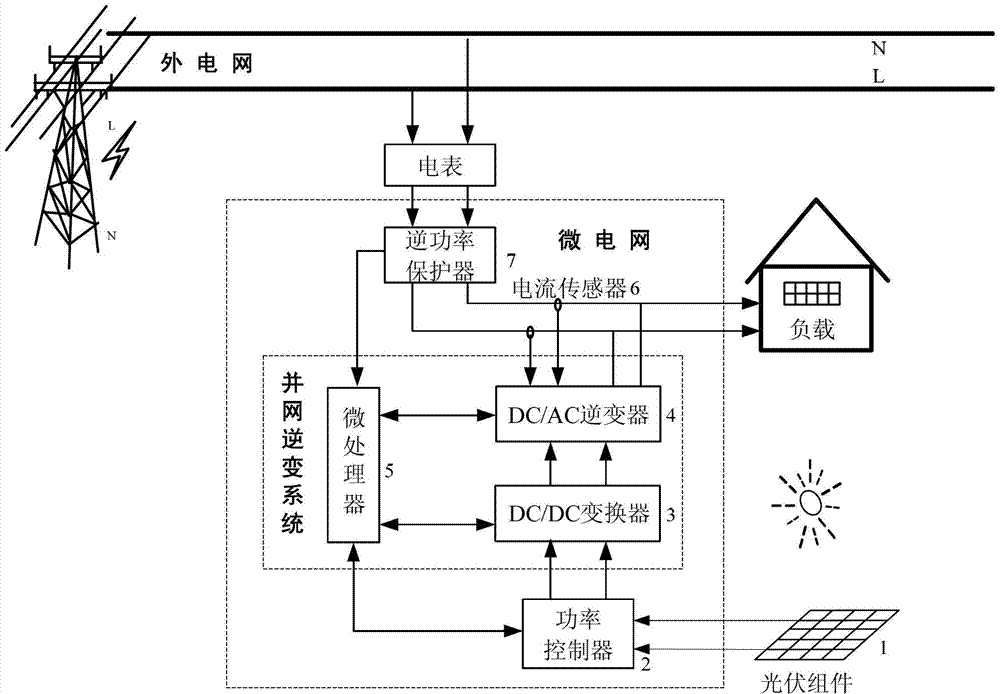
[0030] Such as figure 1 Shows the online microgrid control system. It mainly includes 1, solar photovoltaic panels, 2, power controller, 3, DC/DC converter, 4, DC/AC converter, 5, microprocessor, 6, current sensor, 7, reverse power protector. The structure and connection function of each part are further explained below.
[0031] The solar photovoltaic power generation panel 1 is connected to the grid-connected inverter system (3DC/DC converter 4DC/AC converter 5 microprocessor combination) through the power controller 2, and the output of the inverter system is connected to the grid current to supply power to the load at the same time; The sensor 6 detects the magnitude and phase of the grid current as the current feedback control signal of the inverter system; the reverse power protector 7 is installed behind the meter and located between the microgrid and the external grid to prevent the microgrid from transmitting current to the external grid.
[0032] When the utility power exists, it is always in the grid-connected operation state. When the load power is large, the photovoltaic micro power supply system is at the maximum power output, and it merges with the grid to supply power to the load; when the output power of the photovoltaic micro power supply system is greater than the load power, the power controller adjusts the output power to ensure that the micro power system supplies power to the load. At the same time, the power grid maintains the minimum current as the current feedback of the micro power supply system; when the load power is small, that is, when the power grid maintains the minimum current output power to supply power to the load, the micro power control system stops working.
[0033] In the whole process, the micro power system does not send power to the grid to ensure that there is no impact on the external grid; at the same time, it eliminates the energy storage device. Although the electrical energy may be wasted, it reduces the system cost, is safe and reliable, and achieves the economical efficiency of power saving. The purpose is conducive to promotion.
[0034] Such as figure 2 Is the power controller 2. The power controller hardware uses a buck-boost combination circuit, such as figure 2 Shown. Software implementation adopts the variable step length hill climbing method to make the photovoltaic panel variable power output, that is, output the maximum power or power that matches the load.
[0035] The power controller 2 is implemented by a buck-boost combination circuit, which can boost or buck. Although the commonly used Cuk or Buck-Boost circuits can solve the buck-boost problem, their output reverse pressure, and Cuk circuits need to use non-polar capacitors to transmit energy, which will increase the unreliability and cost of circuit design. The buck-boost combination circuit used in this system is simple and reliable, and can be switched freely by the single-chip microcomputer. Only one boost and buck circuit is working at the same time. Such as figure 2 As shown, when Q1 is turned on and Q2 is controlled as a switching tube, the voltage is boosted; when Q2 is turned off and Q1 is controlled as a switching tube, the voltage is reduced. Changing the duty cycle of the PWM wave output by the single-chip microcomputer to the switching element makes the equivalent load impedance change at will within the range. No matter what the internal resistance of the equivalent power supply is, impedance matching can be achieved. The PWM control signal controls the MOSFET through the IR2011s driver chip.
[0036] The power controller 2 can realize variable power output, and its input is the output voltage V and output current I of the photovoltaic cell. The maximum power tracking control algorithm flow is as follows image 3 Shown.
[0037] Such as Figure 4 Is the overall block diagram of the inverter system, Figure 5 It is a block diagram of the DC/DC converter 3 full bridge circuit structure. The feedback loop is to collect the DC high voltage signal at the DC high voltage output terminal through the DC voltage sensor and feed it back to the UC3875 chip, and compare with the internal standard signal of the UC3875 chip to adjust the phase difference of the four PWM output pulses , And then through the IR2110s driver chip to control the four MOSFETs to adjust the output voltage of the full bridge circuit to stabilize it at a certain value, the set value is 380V, in order to achieve the purpose of closed-loop control and feedback. The protection circuit collects the input DC current through the DC current sensor, and compares it with the overcurrent protection signal threshold inside the UC3875 chip after passing through the signal processing circuit. Once overcurrent, the comparator outputs a high level, UC3875 locks and trips, DC/ DC stops working and completes input overcurrent protection. The main control chip ATmega64 provides UC3875 with a 128KHz synchronization signal and a DC/DC software protection signal.
[0038] When implementing power tracking control algorithms and grid-connected control, it is necessary to detect grid voltage and current and inverter system output current at the same time to implement grid-connected control of the inverter system. At the same time, it detects the DC bus voltage and executes the DC bus constant voltage control algorithm to adjust the inverse. Change the size of the grid-connected output current of the system to achieve the purpose of controlling the DC bus voltage to the pre-specified voltage value. The whole system is a coordinated dynamic process.
[0039] Such as Image 6 It is a block diagram of the DC/AC converter 4 full-bridge inverter circuit structure. The grid-connected inverter adopts current control, the compensation network is PI adjustment, and the current loop adopts current hysteresis instantaneous control technology, that is, the inductor current is used as the feedback amount, which has a strong The anti-load short-circuit ability, and the output voltage waveform quality is higher when the linear load is adopted.
[0040] Such as Figure 7 It is the block diagram of the current PWM feedback control technology structure, the output current i of the inverter converter L After being detected, get the converted voltage signal u IO And the given (reference) reference sine wave voltage u Ir In comparison, the voltage error signal is amplified by the PI voltage regulator to generate the control signal u k , Acting on the unipolar frequency multiplication SPWM pulse width modulation circuit PWM, converting the analog voltage signal into a switching pulse signal, and then driving the power switch tube through the driving circuit, because the width of the pulse signal varies with u k And change, and u k With output current i L And change, thereby changing the output current, forming a single closed-loop current feedback control system.
[0041] The entire inverter system is always grid-connected inverter. To ensure the reliability and safety of grid-connected inverter, the active detection method inside the inverter system is used to avoid possible dangers. Some voltage and frequency disturbances or deviations are artificially added during grid connection to increase the reliability of islanding effect detection.
[0042] The specific method is to actively shift the phase of the grid-connected current waveform every 25 cycles, and then check whether it exists in the next cycle. If the grid is normal, a slight phase shift can still be detected in the next cycle; if the grid fails, the detected grid voltage is the output voltage of the inverter system. If the phase offset is small, it means that islanding effect has occurred, and grid-connected operation should be stopped immediately. . Detecting every 25 cycles can reduce the influence of phase offset on grid-connected waveform.
[0043] The grid current sensor 6 ensures that the inverter current is in the same frequency and phase as the grid current, and supplies power to the load together. At the same time, it judges the magnitude of the current supplied by the grid to the load and determines the mode of operation of the microgrid control system.
[0044] The present invention sets the minimum current threshold value provided by the external power grid to the load as 0.1A, and sets the power provided by the micro-grid to the load as P N , The power provided by the external grid to the load is P W , The power consumed by the load is P L. The online microgrid control system has three working modes:
[0045] Mode 1: When "P N ≤P L "At this time, the microgrid and the external grid supply power to the load at the same time; at this time, the power controller adopts MPPT control technology for the photovoltaic power generation system to ensure that the microgrid system provides the maximum output power to the load, and the insufficient part is supplemented by the external grid. The demand for the power supply of the load can also achieve the purpose of energy saving (reduce the amount of power supplied by the external grid, and save energy as much as possible), that is, P Nmax +P W =P L.
[0046] Mode 2: When "P N ≥P L ", it means that the output power of the microgrid is surplus after satisfying the load consumption. At this time, the system uses a reverse power protector to isolate the connection between the microgrid and the internal grid, preventing the microgrid from delivering current to the external grid, and at the same time, grid-connected inverter The system automatically adjusts (reduces) the power output of the photovoltaic power generation system according to the current feedback signal of the current sensor, so that the microgrid only outputs the power required to meet the load consumption, namely P N +P Wmin =P L.
[0047] Mode 3: When P L Very small, in order to prevent the reverse transmission of power (I N Flow to the external power grid), in the actual program processing of this system, if the current I W When ≤0.1A, the output power P at which the external grid maintains the lowest current W When enough power is supplied to the load, the microprocessor issues an instruction to the microgrid to stop power output, and the external power grid directly supplies power to the load.
[0048] Although the content of the present invention has been described in detail through the above preferred embodiments, it should be recognized that the above description should not be considered as limiting the present invention. After those skilled in the art have read the above content, various modifications and substitutions to the present invention will be obvious. Therefore, the protection scope of the present invention should be defined by the appended claims.

PUM

no PUM

Description & Claims & Application Information

We can also present the details of the Description, Claims and Application information to help users get a comprehensive understanding of the technical details of the patent, such as background art, summary of invention, brief description of drawings, description of embodiments, and other original content. On the other hand, users can also determine the specific scope of protection of the technology through the list of claims; as well as understand the changes in the life cycle of the technology with the presentation of the patent timeline. Login to view more.

Similar technology patents

Classification and recommendation of technical efficacy words

  • Improve conversion efficiency
  • Extend your life

Light-scattering film and optical device using the same

InactiveUS20060137735A1Improve conversion efficiencyPV power plantsDiffusing elementsElectrical resistivity and conductivityConductive materials
Owner:MITSUBISHI HEAVY IND LTD
Why Eureka
Try Eureka