
High-frequency detection pulse injection method of brushless direct current motor

A brushed DC motor, high-frequency detection technology, applied in electronic commutation motor control, single motor speed/torque control, electrical components and other directions, can solve problems such as increasing system cost, motor speed deviation, limiting detection accuracy, etc. Improve accuracy and timeliness, improve low-speed and zero-speed performance, and expand the effect of inductance differences

Active Publication Date: 2012-11-14
TIANJIN UNIV
View PDF5 Cites 15 Cited by
  • Summary
  • Abstract
  • Description
  • Claims
  • Application Information

AI Technical Summary

Problems solved by technology

When detecting the position signal, the driving voltage signal cannot be output, which affects the motion control and speed regulation of the brushless DC motor, resulting in deviation of the motor speed, especially when the motor starts and runs at low speed, the system performance drops seriously; it also affects the high frequency detection The real-time nature of pulse injection results in inaccurate position signals
[0006] Commonly used brushless DC motors have small inductance differences, low signal-to-noise ratio of detection signals, and difficult algorithm implementation
After the power switching element is selected, the maximum switching frequency is fixed, which limits the increase in the frequency of high-frequency detection pulse signals. Traditional methods rely on high-precision current sensors, which increases system costs and limits the improvement in detection accuracy.

Method used


Image

  • High-frequency detection pulse injection method of brushless direct current motor
  • High-frequency detection pulse injection method of brushless direct current motor
  • High-frequency detection pulse injection method of brushless direct current motor

Examples


Embodiment Construction

[0020] The present invention will be further described below in conjunction with accompanying drawings and examples.

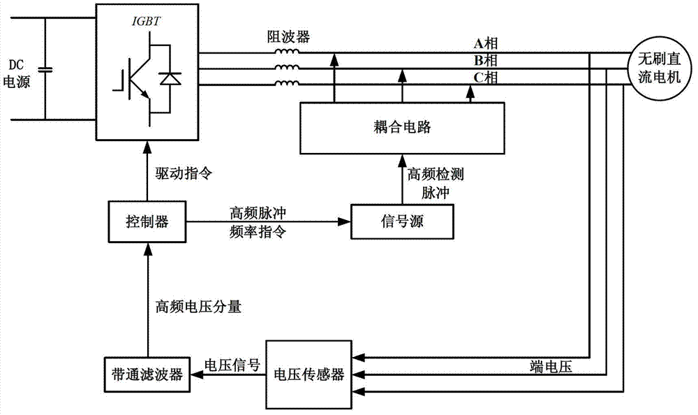
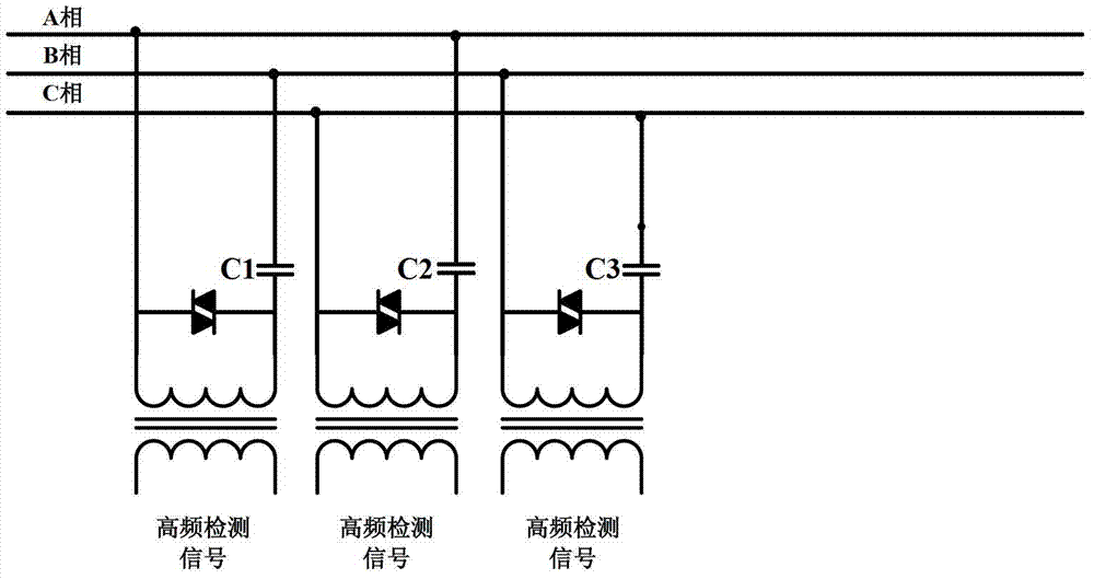
[0021] The principle diagram of the present invention is as figure 1 As shown, the controller, brushless DC motor and power switch are the same as the common brushless DC motor drive system. It can be seen from the figure that there is a set of independent high-frequency detection pulse injection mechanism deployed on the output side of the power switch. The high-frequency detection pulse injection mechanism is composed of a signal source and a coupling circuit. Directly according to the high-frequency signal frequency command of the controller or generated by the signal source in the form of a fixed frequency, the high-frequency signal generated by the signal source is directly transmitted to the power line of the brushless DC motor through the coupling circuit.

[0022] There is a high-frequency signal blocker between the high-frequency pulse injection poin...


PUM


Abstract

The invention belongs to the technical field of brushless direct current motor control and relates to a high-frequency detection pulse injection method of a brushless direct current motor. The method is characterized in that a high-frequency source is utilized for generating high-frequency detection pulse signals, the high-frequency detection pulse signals are respectively coupled onto each phase of power supply wires and windings of the brushless direct current motor through a coupling circuit, each phase of end voltage values of the brushless direct current motor are detected through a voltage sensor, the high-frequency voltage components of each phase of end voltage are obtained from each phase of end voltage values respectively through a band-pass filter, position signals are obtained according to amplitude, phase position or instantaneous value differences of the high-frequency voltage components, and a controller realizes the non-position sensor control of the brushless direct current motor according to the position signals. The high-frequency detection pulse injection method has the advantages that the precision and the real-time performance of detecting signals can be improved, and the system cost is reduced.

Description

Technical field [0001] The invention belongs to the technical field of brushless DC motor control and relates to a high-frequency detection pulse injection method. Background technique [0002] The most fundamental feature of brushless DC motors is that they can be commutated without brushes. According to the position signal, the brushless DC motor relies on the electronic commutator to energize each phase in a certain order, thus eliminating the need for brushes in the motor that are easily damaged and require frequent maintenance, reducing the manufacturing cost and maintenance cost of the motor, and expanding the application scope. The position sensor of the brushless DC motor must be installed inside the motor to detect the position of the motor rotor. The position sensor needs to be maintained and the price is high, which limits the stable and efficient operation of the brushless DC motor under harsh conditions. [0003] The position sensorless control technology of t...

Claims


Application Information

Patent Timeline
IPC IPC(8): H02P6/08H02P6/18H02P6/185
Inventor 夏长亮陈炜李新旻
Owner TIANJIN UNIV
Learn More