Portable electronic cystoscope

A cystoscope, portable technology, applied in the field of portable electronic cystoscope, can solve the problems of insufficient field of view, easy misdiagnosis, observation blind area, etc., and achieve the effect of simple operation, quick installation and easy mastery of the equipment

Active Publication Date: 2012-11-21
HANGZHOU HAWK OPTICAL ELECTRONICS INSTR CO LTD
View PDF7 Cites 3 Cited by
  • Summary
  • Abstract
  • Description
  • Claims
  • Application Information

AI Technical Summary

Problems solved by technology

[0004] The invention provides a portable electronic cystoscope that can effectively conform to the natural physiological curve of the human urethra, has a large field of view, eliminates blind spots in observation, has clear image display, hi

Method used


Image

  • Portable electronic cystoscope
  • Portable electronic cystoscope
  • Portable electronic cystoscope

Examples


Embodiment 1

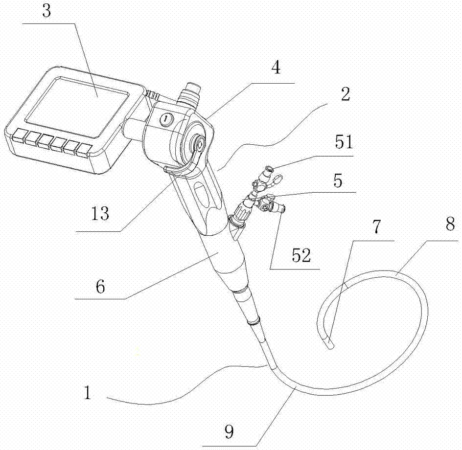
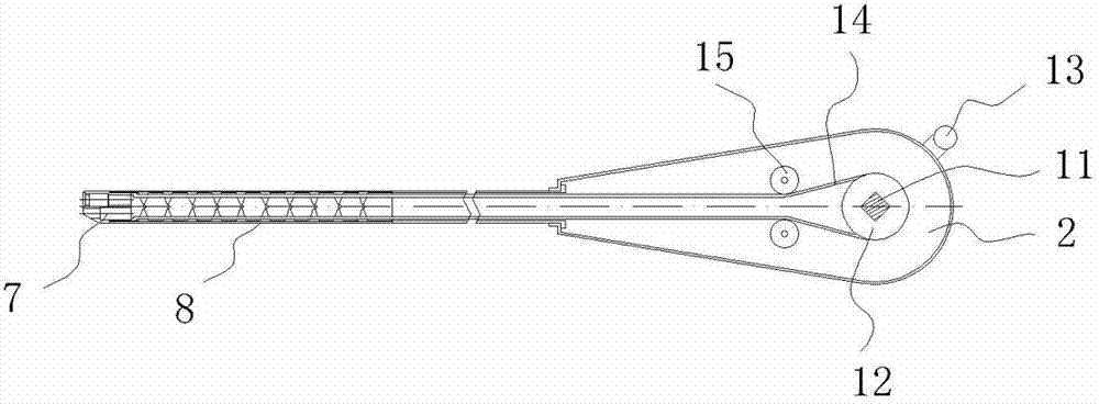
[0029] like figure 1 As shown, a portable electronic cystoscope includes a mirror tube 1 and an operating handle 2 connected with the mirror tube 1 . The operating handle 2 includes an operating body 4 connected to the liquid crystal display 3 and an operating part 6 connected to the mirror tube 1 . The mirror tube 1 is composed of a tip portion 7, a soft bending portion 8 and an insertion portion 9 connected in sequence. The diameter of the mirror tube 1 is 5mm, and its extent is 380mm. The tip part 7 is equipped with a CMOS image sensor and an optical lens, and the soft curved part 8 is formed by a snake bone structure. A lever 13 and a liquid crystal display 3 are fixed on the operating body 4, and a lithium battery is installed on the back of the liquid crystal display 3 for power supply. On one side of the display 3, there are SD card slots, USB data cable ports, charging ports, etc. (not shown in the figure). The driving lever 13 is fixed on the operating body 4 thro...

Embodiment 2

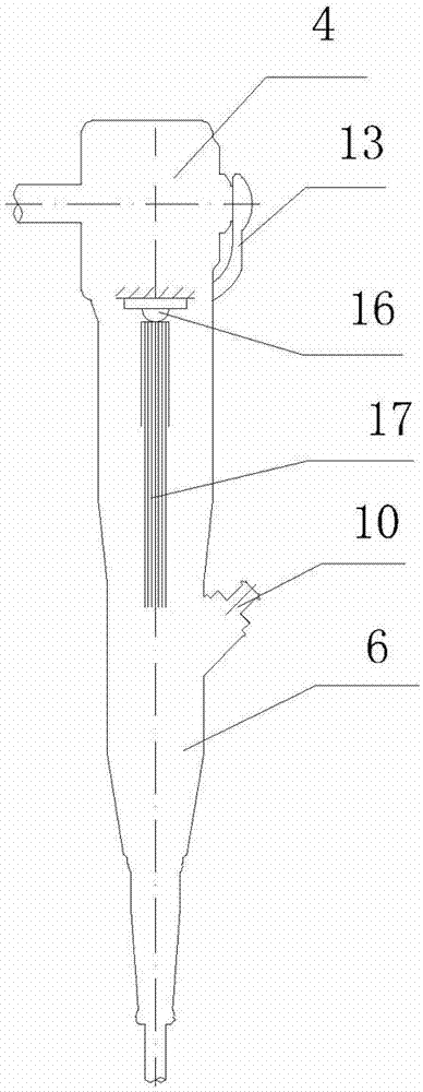
[0033] like Figure 5 As shown, the difference from Embodiment 1 is that an LED lamp 16 is fixed inside the operating handle 2, a lens group 27 is installed below the LED lamp 16, and a light guide 17 is installed below the lens group.

[0034] like Image 6 As shown, the LED lamp 16 is fixed on the substrate 18, and the two leads 19 drawn from the substrate 18 are connected to the lithium battery on the display 3. There is a pressing plate 20 above the base plate 18, and the pressing plate 20 is fixed on the top of the fixing base 22 by screws 21, and the fixing base 22 is fixed on the bottom plate 23 in the operating handle by screws. A through hole 24 is provided in the fixed seat 22, and the through hole 24 is stepped. A lens group 27 consisting of four lenses is installed in the through hole. The parameters of each lens in the lens group 27 are shown in the table below:

[0035] mirror number radius of curvature mirror distance Refractive index n D Di...


PUM

PropertyMeasurementUnit
Light intensityaaaaaaaaaa

Abstract

The invention relates to a medical appliance, in particular to a portable electronic cystoscope clinically used for carrying out examination, diagnosis and treatment on urological diseases on the bladder, the urethra and the like. The portable electronic cystoscope comprises a telescope and is characterized in that the telescope is connected with an operation handle, a display mechanism is connected onto the operation handle, the telescope comprises an insertion part, a soft bending part and a front end part in mutual connection, a lens is arranged at the front end part, an illumination system is arranged in the operation handle and comprises an illumination lamp and a light guide beam connected with the illumination lamp, one end of the light guide beam is connected with the illumination lamp, and the other end of the light guide beam extends to the front end part. The invention simultaneously provides the portable electronic cystoscope with the advantages that the pipe diameter is small, the insertion pain is small, the heating quantity is small, the use is safe, the structure is simple, and the carrying and the work are convenient. The portable electronic cystoscope solves the technical problems that in the prior art, the insertion of the cystoscope is painful, the equipment is huge, the length of the light guide beam is long, and the heating quantity is great.

Description

technical field [0001] The invention relates to a medical device, in particular to a portable electronic cystoscope for clinical examination, diagnosis and treatment of bladder, urethra and other urological diseases. Background technique [0002] At present, cystoscopy is necessary when diagnosing and treating diseases of the urethra and bladder in clinical medicine. Cystoscopy and cystoscopy technology have been widely used clinically and are important tools for urology diagnosis and treatment. At present, many cystoscope inner cores use an optical system in which glass cylindrical lenses are arranged in an orderly manner, and light will inevitably be lost during transmission in the system, which restricts the further improvement of the image transmission system image of the cystoscope optical system. There are usually two types of transmission endoscope lighting methods, one is the fiber optic lighting method, the light source is installed in the controller, and the light ...

Claims


Application Information

Patent Timeline
IPC IPC(8): A61B1/307
CPCA61B1/307A61B1/07A61B1/00108A61B1/00052A61B1/0669A61B1/0684
Inventor 孙颖浩高小峰陈尧松王海丽俞国良
Owner HANGZHOU HAWK OPTICAL ELECTRONICS INSTR CO LTD
Why Eureka
Try Eureka