Combined type precision sheet metal stamping and riveting mould

A punching riveting and combined technology, applied in forming tools, manufacturing tools, metal processing equipment, etc., can solve problems such as increasing production costs, restricting the shape and free space of processing plates, and complex riveting process, and achieves stamping riveting technology. Improve and overcome the effects of low riveting efficiency and simplified mold structure

Inactive Publication Date: 2012-11-21
JIANGSU UNIV
View PDF6 Cites 8 Cited by
  • Summary
  • Abstract
  • Description
  • Claims
  • Application Information

AI Technical Summary

Problems solved by technology

[0003] In general, the riveting method between metal plates is mainly rivet riveting. Its process includes: 1) punching holes in the corresponding positions of the two metal plates; Metal plate; 3) Use stamping equipment to punch the headless end of the rivet into a flange shape, and fix the two sheets together; this method needs to punch positioning holes on the metal plate in advance to ensure positioning, which will increase the process and improve Production cost, and positioning holes will be left on the board after riveting, which is not beautiful, making the riveting process complicated, poor in appearance, low in efficiency and difficult to automate
[0004] Commonly used punching and riveting dies are composed of simple punches, blank holders and dies. Before each punching, the centering of the punching and concave dies is manually adjusted. The lack of precise punching and riveting guidance and positioning in the process greatly reduces the production of the dies. Efficiency; although the conventional stamping mold frame and the mold made by the template ensure the positioning of the convex and concave molds, it limits the shape of the processed plate and the free space for processing

Method used


Image

  • Combined type precision sheet metal stamping and riveting mould
  • Combined type precision sheet metal stamping and riveting mould
  • Combined type precision sheet metal stamping and riveting mould

Examples


Embodiment Construction

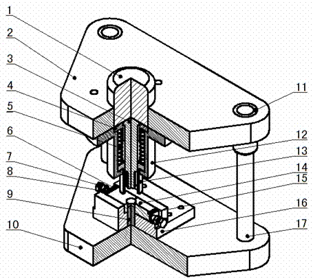
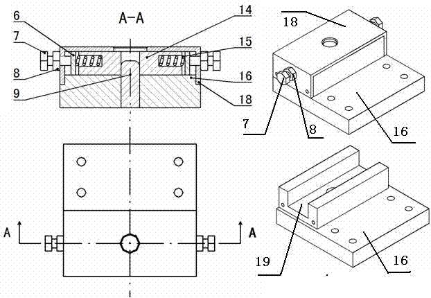
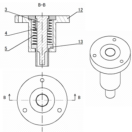
[0015] Depend on figure 1 It can be seen that the main components of the patented stamping and riveting die of the present invention include: upper die assembly I, lower die assembly II and mold base. Depend on image 3 It can be seen that the upper die assembly I includes: punch 3, punch sleeve 4, spring 5, spring sleeve 12, blank holder ring 13; figure 2 It can be seen that the lower die assembly II includes: a baffle plate 6, an adjusting screw 7, a lock nut 8, a die upset 9, a split die 14, a spring member 15, a die plate 16, and a die cover 18. The mold base includes: mold handle 1, upper mold base 2, lower mold base 10, guide sleeve 11, guide post 17; the assembly relationship is: lower mold assembly II is fixed on lower mold base 10, upper mold assembly I and mold The handle 1 is fixed on the upper mold base 2, the guide post and guide sleeve adopt the rear type, the guide post 17 and the lower mold base 10 have an interference fit, the guide sleeve 11 and the upper ...


PUM


Abstract

The invention relates to a combined type precision sheet metal stamping and riveting mould, belonging to the field of pressed deformation connection and mould in mechanical engineering. The combined type precision sheet metal stamping and riveting mould comprises a guide device which comprises a postposed guide pillar and a guide sleeve, a precise upper mould and a precision lower mould to realize the precise stamping and riveting process so as to improve the loading and unloading efficiency of the sheet metal in the mould. The combined type precision sheet metal stamping and riveting mould can overcome the quality defects that riveting joints are asymmetric, riveting gaps appear in the riveting process, and that the riveting joints are easy to pull off and realizes a single-gate shearing-free stamping and riveting process; riveting joints with high strength, high rigidity, rotational symmetry and even stress can be formed; and the self-locking ability of the riveting joints is improved. The height increase of the riveting joint at the concave mould is small and the riveting joint at the concave mould is more attractive. The stamping force required by the convex mould is relatively small, so the combined type precision sheet metal stamping and riveting mould is suitable for a general punch press. The combined type precision sheet metal stamping and riveting mould is simple in structure and convenient to operate, saves installing and debugging man-hour, improves the labor productivity and thereby increases the economic benefit.

Description

technical field [0001] The patent of the invention relates to a combined precision sheet metal stamping and riveting die, which belongs to the technical field of pressure deformation connection and die in mechanical engineering. Background technique [0002] With the development of the machinery industry, more and more attention has been paid to the economy of mechanical products, and the manufacturability of mechanical products also requires precision, high efficiency, automation, etc.; the connection of two metal plates plays an important role in realizing mechanization and automation. reality and long-term significance. [0003] In general, the riveting method between metal plates is mainly rivet riveting. Its process includes: 1) punching holes in the corresponding positions of the two metal plates; Metal plate; 3) Use stamping equipment to punch the headless end of the rivet into a flange shape, and fix the two sheets together; this method needs to punch positioning ho...

Claims


Application Information

Patent Timeline
Patent Type & Authority Applications(China)
IPC IPC(8): B21D37/10B21D39/02
Inventor 陈炜赵昊张杨刘政陈志峰
Owner JIANGSU UNIV
Why Eureka
Try Eureka