Electro-hydraulic braking system and control method thereof

A brake system, electronically controlled hydraulic technology, applied in the direction of hydraulic brake transmission, brake, brake transmission, etc., to achieve good safety performance, save energy consumption, and improve braking safety.

Inactive Publication Date: 2012-11-21
郑州宇通集团有限公司
View PDF5 Cites 32 Cited by
  • Summary
  • Abstract
  • Description
  • Claims
  • Application Information

AI Technical Summary

Problems solved by technology

Therefore, the EHB system in this patent basically does not need the battery to provide electric energy during the braking p

Method used


Image

  • Electro-hydraulic braking system and control method thereof
  • Electro-hydraulic braking system and control method thereof

Examples


Embodiment Construction

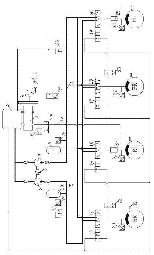
[0016] The working and control mode of the electronically controlled hydraulic braking system of the present invention will be described in detail below in conjunction with the accompanying drawings.

[0017] Such as figure 1 The electronically controlled hydraulic braking system (referred to as "EHB system") shown includes a brake pedal simulator formed by a brake pedal 1 and a brake master cylinder 2, an oil storage tank 3, and two hydraulic pumps 7 , 8. A motor 6, a high-pressure accumulator 9, a low-pressure accumulator 10, and a hydraulic control unit (HCU) formed by several solenoid valves, and an electronic control unit (HCU) composed of an electronic controller, several sensors, and a bus ( ECU). A stroke sensor 4 is arranged at the brake pedal 1 . The oil storage tank 3 is respectively connected with two hydraulic pumps 7, 8, both of which are connected with the electric motor 6, and the electronic controller is connected with the electric motor 6, several sensors ...


PUM


Abstract

The invention discloses an electro-hydraulic braking system and a control method thereof for an electric automobile. The electro-hydraulic braking system is provided with a high-voltage brake circuit, a low-voltage brake circuit and a standby brake circuit, wherein the high-voltage brake circuit comprises a first hydraulic pump, a high-voltage energy accumulator, a three-position and three-way valve and a corresponding brake wheel cylinder which are sequentially connected; a pressure sensor is arranged near a pipeline at an output rear end of the high-voltage energy accumulator; the low-voltage brake circuit comprises a second hydraulic pump, a low-voltage energy accumulator, a three-position and three-way valve and a corresponding brake wheel cylinder which are sequentially connected; when the pressure of the pressure sensor is lower than a preset value; the first hydraulic pump sucks hydraulic oil and pumps the hydraulic oil into the high-voltage energy accumulator for enabling the automobile to brake; the second hydraulic pump sucks hydraulic oil and pumps the hydraulic oil into the low-voltage energy accumulator for enabling the automobile to brake; when the brake strength is higher than the brake strength which can be provided by the low-voltage brake circuit, the high-voltage brake circuit is started; when the brake strength which can be provided by the low-voltage brake circuit meets the required brake strength, a low-voltage brake mode is started; and a favorable safety performance is obtained and brake energy can be recovered to the maximum extent.

Description

technical field [0001] The invention relates to a braking system in the field of automobiles, in particular to an electronically controlled hydraulic braking system used in electric vehicles. Background technique [0002] The braking system in existing automobiles has problems such as slow response of braking force, low accuracy of braking force control, and failure to meet braking performance requirements under emergency braking conditions. With the gradual introduction of control-by-wire technology into the design and development of automobiles, the electrohydraulic braking system (EHB) has suddenly emerged due to its advantages. The EHB system is composed of electronic brake pedal module, hydraulic control unit (HCU), electronic control unit (ECU) and other parts. The brake hydraulic pressure in the wheel cylinder is no longer generated by the driver's pedal force to drive the brake master cylinder, but the ECU controls the high-speed electromagnetic liquid inlet valve ...

Claims


Application Information

Patent Timeline
IPC IPC(8): B60T13/74B60T13/66B60T11/16
Inventor 何仁胡东海
Owner 郑州宇通集团有限公司
Why Eureka
Try Eureka