
Fluid pump with screw spiral mechanism, fluid power machine and internal and external combustion jet engine

A technology of jet engine and power engine, applied in liquid fuel engine, internal combustion piston engine, rotary or oscillating piston engine, etc., can solve the problems of gap leakage, small compression and high manufacturing cost

Inactive Publication Date: 2012-11-21
周觉明
View PDF0 Cites 0 Cited by
  • Summary
  • Abstract
  • Description
  • Claims
  • Application Information

AI Technical Summary

Problems solved by technology

[0002] The current volumetric rotary-translational mechanism is mainly used for scroll compressors that compress gas. This mechanism has the characteristics of simple structure, small volume, light weight, few parts, small torque change and stable operation because it does not have a reciprocating mechanism. There are still many deficiencies, such as gap leakage, small compression ratio, unfavorable structure and many other factors. It has not been popularized in the field of compressors, and it cannot be applied in the field of fluid transportation and power technology. Large and stable operation, but there are factors such as complex structure and high manufacturing cost. The purpose of the present invention is to combine the working characteristics of scroll compressors and screw compressors to provide a screw worm fluid pump power machine and engine with a volumetric rotary translation mechanism. and jet engines, replacing and eliminating fluid transfer pumps, compressors, hydraulic power machines, steam power machines, engines and jet engines currently in use

Method used


Image

  • Fluid pump with screw spiral mechanism, fluid power machine and internal and external combustion jet engine
  • Fluid pump with screw spiral mechanism, fluid power machine and internal and external combustion jet engine
  • Fluid pump with screw spiral mechanism, fluid power machine and internal and external combustion jet engine

Examples


Embodiment Construction

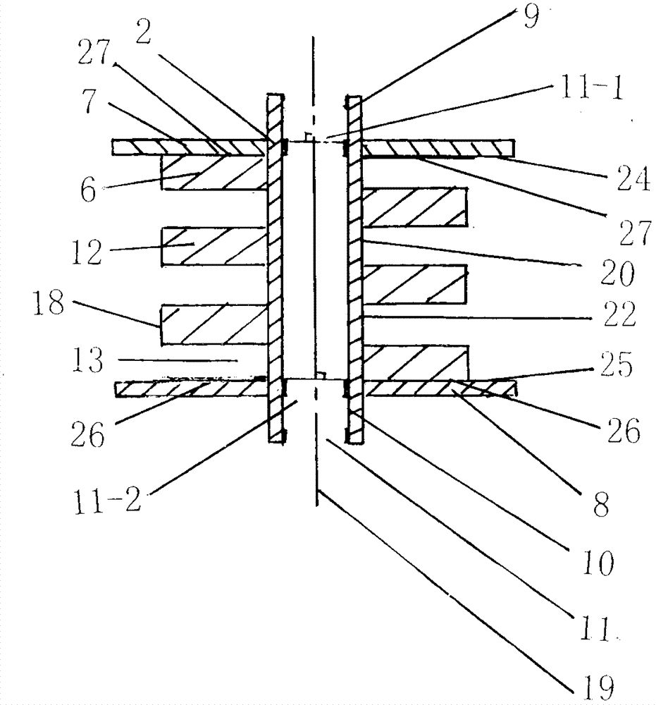
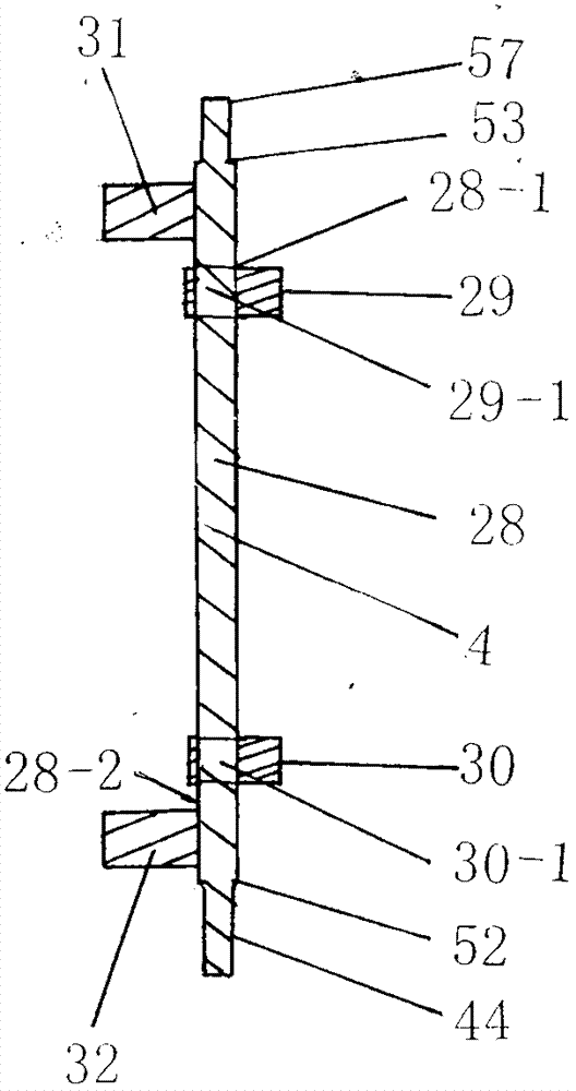
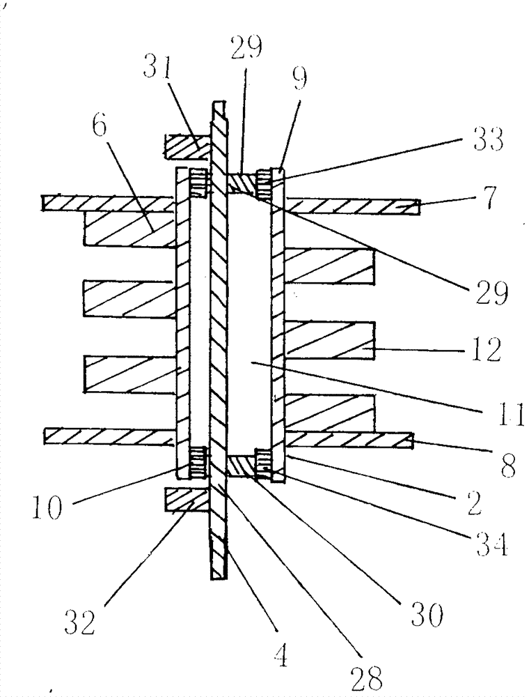
[0038] Screw and worm mechanism of the present invention 1 such as Figure 5 As shown, it is composed of a revolving screw body 2, an eccentric transmission member 4, a volute casing 3, an upper anti-rotation mechanism 5 and a lower anti-rotation mechanism 5-1. Such as figure 1 As shown, the revolving screw body 2 is composed of a screw rod 6, an upper moving plate 7, a lower moving plate 8, an upper shaft housing 9 and a lower shaft housing 10; as figure 1 As shown, the rod core 21 of the screw rod 6 has a hollow portion 11, the upper end 11-1 of the hollow portion 11 of the rod core 21 is fixed with the upper shaft shell 9, and the lower end 11-2 is fixed with the lower shaft shell 10, the rod core of the screw rod 6 The outer wall surface 22 of 21 has the helix 12 surrounded by the clockwise or counterclockwise direction helical line, the outer wall surface 22 top of the rod core 21 is fixed with the upper moving plate 7, the lower translation surface 24 of the upper movin...


PUM


Abstract

The invention discloses a fluid pump with a screw spiral mechanism (1), a fluid power machine, and an internal and external combustion jet engine. The screw spiral mechanism (1) comprises a swiveling screw body (2), a spiral casing (3), an eccentric driving member (4), an upper anti-rotation mechanism (5) and a lower anti-rotation mechanism (5-1); a screw (6) of the swiveling screw body (2) is sleeved in a spiral sleeve (36) of the spiral casing (3); a screw edge (12) of the screw (6) is coupled with a spiral groove (65) of the spiral sleeve (36) to form a spiral surrounding outer cavity (74); and an inner screw edge (54) of the spiral sleeve (36) is coupled with a screw groove (13) of the screw (6) to form a spiral surrounding inner cavity (86). Fluid transport, compression or expansion jet is carried out by the fluid pump, the fluid power machine, and the internal and external combustion jet engine through regular changes of the volume of the outer cavity (74) and the inner cavity (86).

Description

technical field [0001] The screw and worm mechanism is a volumetric rotary-translational structure, and its technical application involves the technical fields of fluid delivery pumps, compressed air pumps, hydraulic power machines, pneumatic motors, external combustion power machines, internal combustion engines and jet engines. Background technique [0002] The current volumetric rotary-translational mechanism is mainly used for scroll compressors that compress gas. This mechanism has the characteristics of simple structure, small volume, light weight, few parts, small torque change and stable operation because it does not have a reciprocating mechanism. There are still many deficiencies, such as gap leakage, small compression ratio, unfavorable structure and many other factors. It has not been popularized in the field of compressors, and it cannot be applied in the field of fluid transportation and power technology. Large and stable operation, but there are factors such a...

Claims


Application Information

Patent Timeline
IPC IPC(8): F04C2/107F04C18/107F01C1/107F02G1/00F02B53/00F02K5/00F03C2/22
CPCY02T10/17Y02T10/12
Inventor 周觉明
Owner 周觉明
Learn More