Single-phase ground fault section positioning method of small-current ground system

A single-phase ground fault, small current grounding technology, applied in the direction of fault location, measurement of electricity, measurement of electrical variables, etc., can solve the problems of low detection accuracy, poor fault detection effect, low detection accuracy, etc., and achieve high anti-interference ability , good versatility, and high detection accuracy

Inactive Publication Date: 2012-11-21
HENAN POLYTECHNIC UNIV
View PDF8 Cites 41 Cited by
  • Summary
  • Abstract
  • Description
  • Claims
  • Application Information

AI Technical Summary

Problems solved by technology

The traveling wave method cannot solve the problem of accurate extraction of transient traveling wave components, identification and calibration of reflected waves at fault points, determination of wave velocity, calibration of arrival time of initial traveling wave surge, etc.
The signal injection method is suitable for systems where only two-phase current transformers are installed on the line. The injected signal is greatly affected by factors such as voltage transformer capacity, grounding resistance, and intermittent arcing, and the fault detection effect is poor.
The outdoor fault point detection method determines the fault point according to the magnitude of the magnetic field generated by the zero-sequence current before and after the grounding point, but the detection accuracy is not high
The impedance method is greatly affected by factors such as path impedance, line load, and power...

Method used


Image

  • Single-phase ground fault section positioning method of small-current ground system
  • Single-phase ground fault section positioning method of small-current ground system
  • Single-phase ground fault section positioning method of small-current ground system

Examples


Embodiment

[0081] Figure 8 It is the radial small current grounding system described in the embodiment of the present invention. Such as Figure 8 As shown, in this embodiment, the line parameters are: positive sequence impedance Z 1 =0.17+j0.38Ω / km, positive sequence ground admittance b 1 =j3.045us / km, zero sequence impedance Z 0 =0.23+j1.72Ω / km, zero sequence ground admittance b 0 =j1.884us / km, the length of each load branch line is r 1 =20km, r 2 =15km, r 3 =24km, r 4 = 8km, r 5 =16km, r 6 = 30km. Transformer parameters are: Δ / Y connection, primary side voltage 220KV, secondary side voltage 35KV, rated capacity S N =40000KVA, the no-load loss is 35.63KW, and the leakage impedance of the primary winding is Z 1g =0.4+j12.2Ω, the leakage impedance of the secondary winding is Z 2g =0.006+j0.183Ω, the steady-state excitation current is 0.672A, the main magnetic flux is 202.2Wb, and the excitation impedance is 400kΩ. The parameters of the arc suppression coil of the transform...


PUM


Abstract

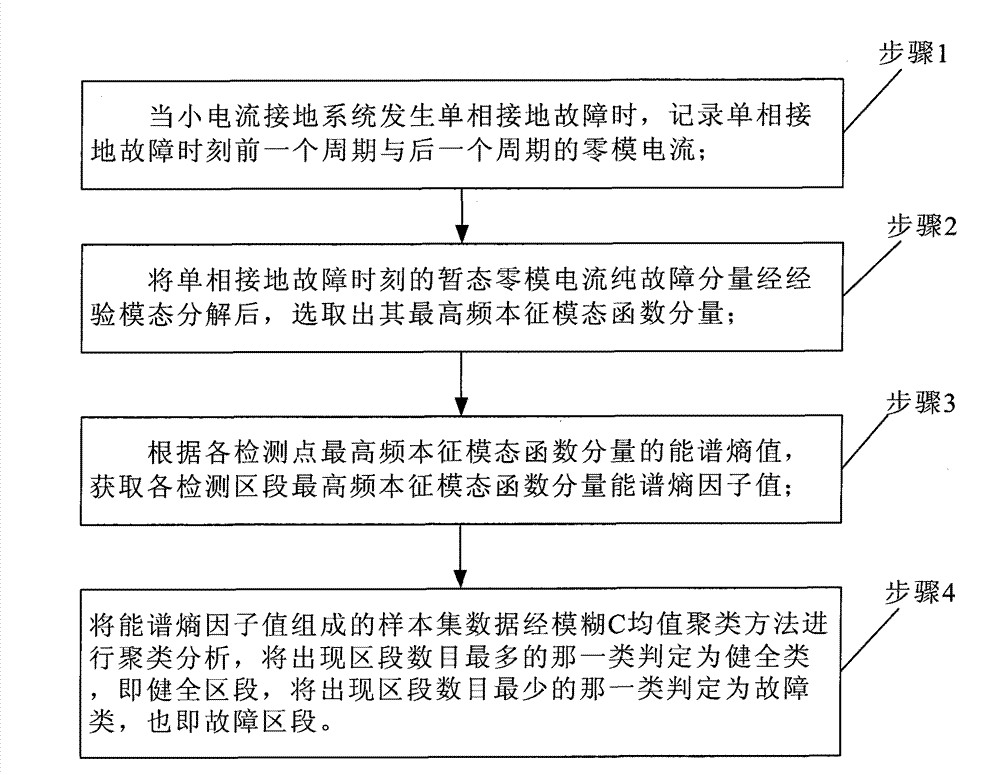
The invention provides a single-phase ground fault section positioning method of a small-current ground system. The single-phase ground fault section positioning method comprises the steps of: 1) when the small-current ground system has a single-phase ground fault, recording zero-mode current of a previous cycle and zero-mode current of a next cycle at the moment when the single-phase ground fault occurs; 2) after a pure fault component of transient zero-mode current at the moment when the single-phase ground fault occurs is decomposed through an empirical mode, selecting out a highest-frequency intrinsic mode function component; 3) according to energy spectrum entropy of the highest-frequency intrinsic mode function component of each detection point, obtaining energy spectrum entropy factor values of the highest-frequency intrinsic mode function component of each detection section; and 4) conducting cluster analysis to sample set data consisting of the energy spectrum entropy factor values through a fuzzy C-means clustering method, determining a kind of sections which occur the most as a sound kind, i.e. sound sections, and determining a kind of sections which occur the least as a fault kind, i.e. fault sections. The single-phase ground fault section positioning method of the small-current ground system has the characteristics of high detection accuracy and good universality, and can be widely used in power systems.

Description

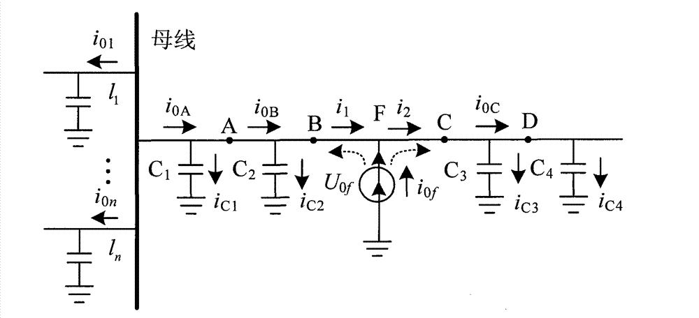
technical field [0001] The invention relates to a distribution network fault diagnosis technology, in particular to a method for locating a single-phase ground fault section of a small current ground system. Background technique [0002] In recent years, the fault location research work of high-voltage transmission lines has made great progress, and the distance measurement devices developed have been popularized and used in the national power grid, and good results have been achieved. However, compared with the high-voltage transmission network, the low-current grounding system has more branch lines, complex network topology, and is easily affected by transition resistance, etc., and the transmission distance of the small-current grounding system is relatively short, so it is still impossible to achieve high-precision fault location . [0003] At present, generally speaking, the research on fault location of small current grounding systems has the following methods: travel...

Claims


Application Information

Patent Timeline
IPC IPC(8): G01R31/02G01R31/08
Inventor 王晓卫田书李玉东张玉均王帅张立威高杰余建芮魏向向
Owner HENAN POLYTECHNIC UNIV
Why Eureka
Try Eureka