Circular polarization satellite navigation antenna, preparation method and antenna circuit
A technology of satellite navigation antenna and antenna circuit, which is applied in the direction of antenna, antenna grounding switch structure connection, electrical components, etc. It can solve the problems of low circular polarization bandwidth, narrow impedance bandwidth, and difficulty in satisfying satellite navigation receivers, etc., and achieve electric field Evenly distributed, the effect of increasing bandwidth and gain
- Summary
- Abstract
- Description
- Claims
- Application Information
AI Technical Summary
Problems solved by technology
Method used
Image
Examples
preparation example Construction
[0068] In the preparation method provided by the present invention, a microstrip line is etched on one side of a double-sided microwave substrate to form an N equal power division phase shifter, the surface is brushed with a layer of anti-oxidation coating as the top surface, and the other side is subjected to conductive treatment as the bottom surface. Connect the bottom surface of the double-sided microwave substrate to the metal ground plate, and connect the short sides of N L-shaped feed probes of the same size to the two outputs of the N equal power divider phase shifter located on the top surface of the double-sided microwave substrate. The end is connected and perpendicular to the double-sided microwave substrate, and at the same time, the N long sides of the N L-shaped feeding probes are mutually 90°, and the first circular patch is insulated and fixedly connected to the double-sided microwave substrate. And located above N L-shaped feeding probes of the same size, and ...
Embodiment 1
[0072] This embodiment mainly describes a circular polarization satellite navigation antenna circuit.
[0073] An N equal power dividing phase shifter, N L-shaped feeding probes of the same size and a first circular patch.
[0074] The short sides of N L-shaped feed probes are respectively connected to the N output terminals of N equal power divider phase shifters, and the long sides are 90° to each other. The first circular patch is placed on N L-shaped feed probes , and the intersection of the long side extension lines of the N L-shaped feeding probes is on the central axis of the first circular patch.
[0075] The N equal power divider phase shifter divides the input energy into N signals with the same amplitude and 90° phase difference, and the N signals are respectively coupled and fed to the first circular patch through N L-shaped feeding probes.
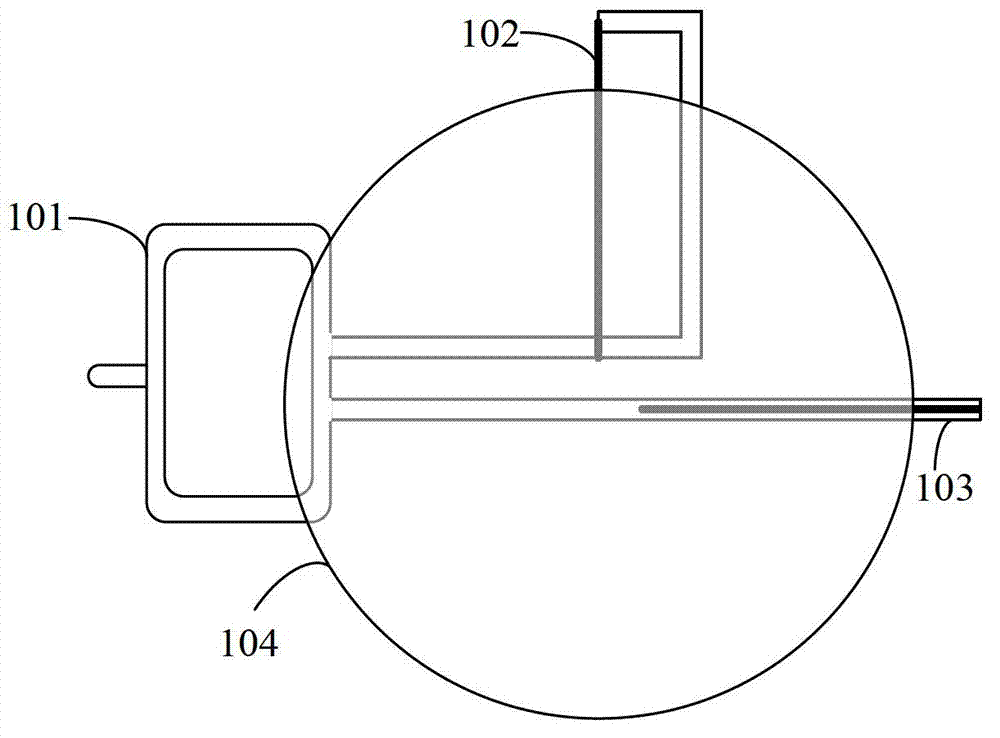
[0076] When N is two, figure 1 It is a top view of a circularly polarized satellite navigation antenna circuit, figure 2...
Embodiment 2
[0090] This embodiment mainly illustrates a method for preparing a circularly polarized satellite navigation antenna.
[0091] Etching microstrip lines on one side of a double-sided microwave substrate to form an N equal power division phase shifter, brushing a layer of anti-oxidation coating on the surface as the top surface, and conducting conductive treatment on the other side as the bottom surface.
[0092] When N is two, such as figure 1 As shown, etched on a double-sided microwave substrate figure 1 The microstrip line of the shape shown in the halving power divider phase shifter 101 is composed of a feed network formed by cascading the halving power divider and the 90° phase shifter.
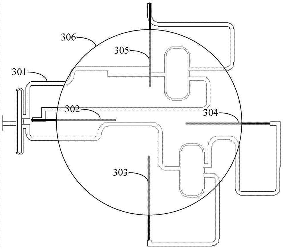
[0093] When N is four, such as image 3 As shown, etched on double-sided microwave substrate image 3 The microstrip line of the shape shown in constitutes a quarter power divider phase shifter 301, and a first-stage feed network is formed by cascading two power dividers and a 180° pha...
PUM
| Property | Measurement | Unit |
|---|---|---|
| Radius | aaaaa | aaaaa |
| Bandwidth | aaaaa | aaaaa |
Abstract
Description
Claims
Application Information
 - R&D Engineer
- R&D Manager
- IP Professional
- Industry Leading Data Capabilities
- Powerful AI technology
- Patent DNA Extraction
Browse by: Latest US Patents, China's latest patents, Technical Efficacy Thesaurus, Application Domain, Technology Topic, Popular Technical Reports.
© 2024 PatSnap. All rights reserved.Legal|Privacy policy|Modern Slavery Act Transparency Statement|Sitemap|About US| Contact US: help@patsnap.com


