Digital linear servo pump

A servo pump, digital technology, applied in the field of digital linear servo pumps, can solve the problems of high cost, low drive efficiency, heat generation, etc., achieve high drive stiffness and precision, overcome heat generation problems, and improve the effect of smoothness

Inactive Publication Date: 2012-11-28
路文忠
7 Cites 2 Cited by

AI-Extracted Technical Summary

Problems solved by technology

[0005] figure 2 Compared with the servo motor ball screw drive mode, the electro-hydraulic servo drive mode shown has the following advantages: high driving rigidity, high positioning accuracy, and fast dynamic response; its disadvantages are: (1) The drive efficiency is low, only 38% at most , so it will gene...

Abstract

The invention relates to a digital linear servo pump comprising a numerical control system, a comparator and a servo amplifier which are connected in sequence, wherein the output of the servo amplifier is connected with a linear oil pump; the linear oil pump is connected with a first oil cylinder group through a pipeline; a piston of the first oil cylinder group is connected with a machine table and used for driving the same; and the machine table is connected with the comparator through an optical grating. The linear oil pump is sequentially connected with a servo motor, a ball screw and a second oil cylinder group, wherein the input end of the servo motor is connected with the output end of the servo amplifier, and the second oil cylinder group is connected with the first oil cylinder group through a pipeline. The second oil cylinder group is also connected with an energy accumulator respectively through a first one-way valve and a second one-way valve. By using the digital linear servo pump, higher driving rigidity and precision can be obtained, and the locating precision can be up to at most 0.001mm. The machine machining smoothness can be improved, the work reliability can be greatly improved, but the cost is greatly reduced.

Application Domain

Feeding apparatusPump installations +1

Technology Topic

PistonNumerical control system +4

Image

  • Digital linear servo pump
  • Digital linear servo pump
  • Digital linear servo pump

Examples

  • Experimental program(1)

Example Embodiment

[0027] In order to further understand the content, features and effects of the present invention, the following embodiments are given as examples, and detailed descriptions are as follows with accompanying drawings:
[0028] The digital linear servo pump of the present invention combines a servo motor, a ball screw and an oil cylinder to form a digital linear servo pump.
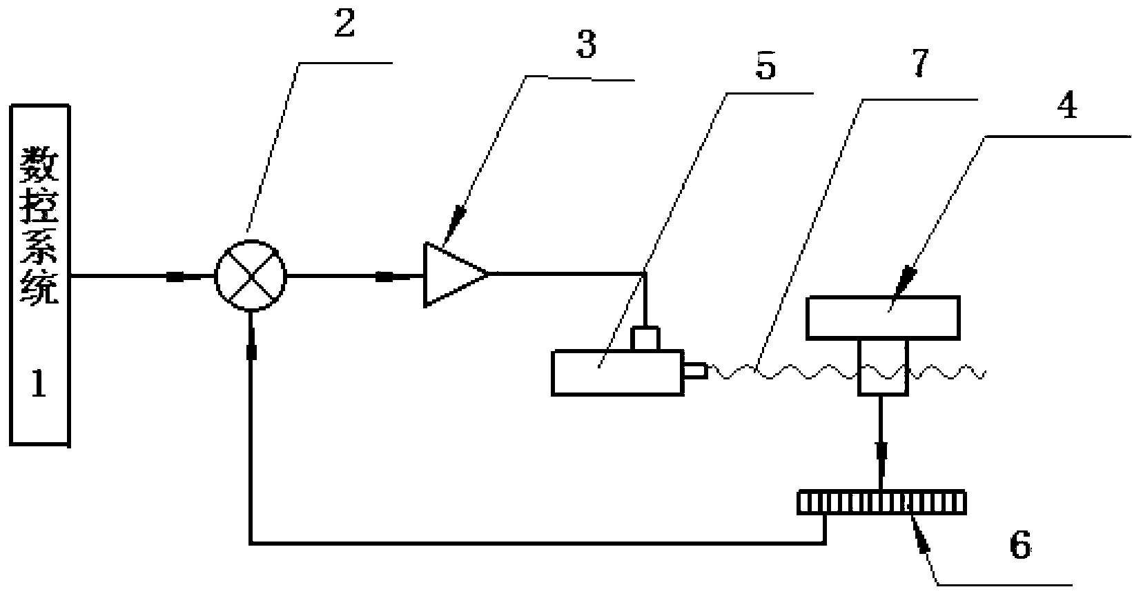
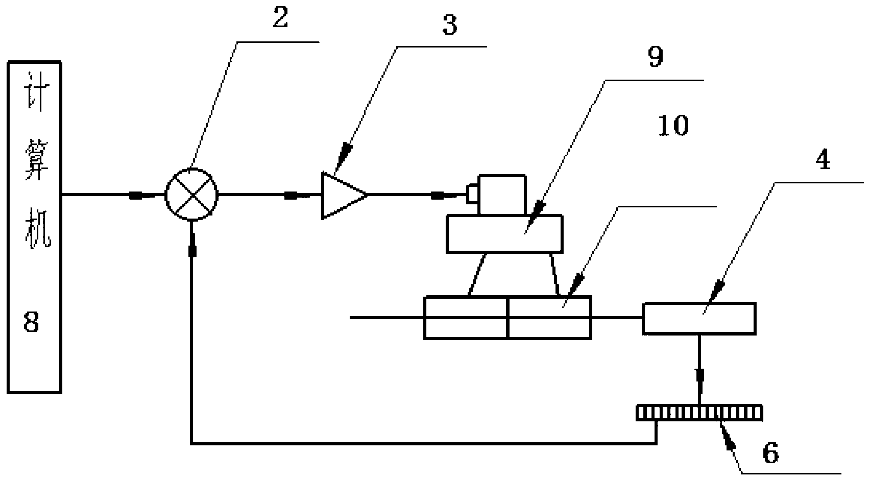
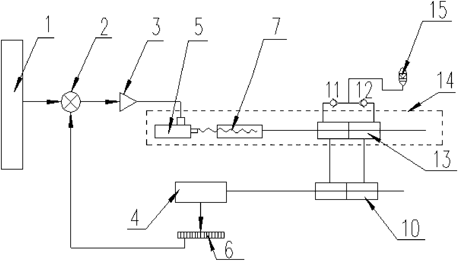
[0029] Such as image 3 As shown, the digital linear servo pump of the present invention includes a numerical control system 1, a comparator 2, and a servo amplifier 3 connected in sequence. The output of the servo amplifier 3 is connected to a linear oil pump 14, and the linear oil pump 14 passes through a pipeline The first oil cylinder group 10 is connected, and the piston of the first oil cylinder group 10 is connected to and drives the machine tool worktable 4, and the machine tool worktable 4 is connected to the comparator 2 through the grating 6.
[0030] The linear oil pump 14 includes a servo motor 5, a ball screw 7 and a second cylinder group 13 connected in sequence, wherein the input end of the servo motor 5 is connected to the output end of the servo amplifier 3, The second cylinder group 13 is connected to the first cylinder group 10 through pipelines, and the second cylinder group 13 is also connected to the accumulator 15 through the first one-way valve 11 and the second one-way valve 12 respectively.
[0031] Such as image 3 As shown, in actual work, the command signal issued by the numerical control system 1 enters the servo amplifier 3 through the comparator 2 and drives the servo motor 5 to rotate after amplification. The servo motor 5 drives the ball screw 7 to push the second cylinder group 13 in the corresponding direction The linear movement of the second cylinder group 13 pressurizes the oil in one cavity and enters the corresponding cavity of the first cylinder group 10. The moving parts of the first oil cylinder group 10 move in the opposite direction of the moving parts of the second oil cylinder group 13 to push the worktable 4 to move. The grating 6 detects the moving amount of the worktable 4 and converts it into an electric signal and sends it to the comparator 2. When the signal of the grating 6 enters the pulse number of the comparator 2 and the command pulse number of the numerical control system 1 is equal, that is, when the output of the comparator 2 is zero, the servo motor 5 stops moving, the ball screw 7 stops moving, and the second cylinder group The piston rod of 13 stops moving, and the second cylinder group 13 stops discharging oil, the first cylinder group 10 stops moving, and the workbench 4 stops moving. When the numerical control system 1 outputs a pulse signal in the opposite direction, the servo motor 5 and the ball screw 7 move in the opposite direction, and the second oil cylinder group 13 and the first oil cylinder group 10 move in response.
[0032] After a certain period of work, that is, after a certain number of reciprocating movements, the hydraulic oil in the second cylinder group 13 and the first cylinder group 10 will have a small amount of loss, in the second cylinder group 13 and the first cylinder group 10 Cavitation will appear in the low-pressure chamber, which will affect its normal operation. When this happens, the accumulator 15 will pass through the first check valve 11 and the second check valve 12 to the second cylinder group 13 and the first cylinder. The low pressure chamber of group 10 supplies oil.
[0033] Because the digital linear oil pump of the present invention has a volumetric efficiency of over 99.9%, it has high rigidity and positioning accuracy, and can realize <0.001mm, can be achieved with figure 2 The solution shown uses the electro-hydraulic servo valve to control the same stiffness and precision, but the reliability is much higher than that of the electro-hydraulic servo valve, and its manufacturing cost is greatly reduced. The positioning accuracy can greatly improve the processing finish.

PUM

no PUM

Description & Claims & Application Information

We can also present the details of the Description, Claims and Application information to help users get a comprehensive understanding of the technical details of the patent, such as background art, summary of invention, brief description of drawings, description of embodiments, and other original content. On the other hand, users can also determine the specific scope of protection of the technology through the list of claims; as well as understand the changes in the life cycle of the technology with the presentation of the patent timeline. Login to view more.

Similar technology patents

Fresh purple sweet potato regenerated rice and preparation method thereof

InactiveCN106690063AImprove the finishUniform water absorption
Owner:HUBEI UNIV OF TECH

Grinding wheel component for tree barking machine

InactiveCN103600277AImprove the finish
Owner:SUZHOU WUZHONG DISTRICT GUANGFU XIANGXUE NURSERY GARDEN

Door brick of coke oven and preparation process thereof

InactiveCN1560193AImprove the finisheasy to remove tar
Owner:山东耐材集团中齐耐火有限公司

Preparation method of nano composite aluminum oxide for filling rubber

ActiveCN106633224AImprove the finishImproved heat and impact resistance
Owner:河北观驰新材料科技有限公司

Classification and recommendation of technical efficacy words

  • Improve the finish

Guide nut tooth lost foam casting method

InactiveCN104874738AAvoid errorsImprove the finish
Owner:山西威龙铁路机车制动配件制造有限公司

Forming process of seed crystal bar chuck

InactiveCN1362544AGood coaxialityImprove the finish
Owner:SHANGHAI INST OF OPTICS & FINE MECHANICS CHINESE ACAD OF SCI
Why Eureka
Try Eureka